
Installation Guide
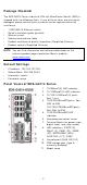
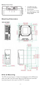
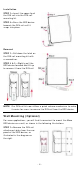
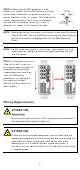
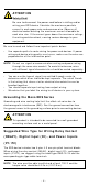
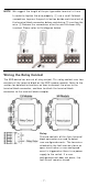
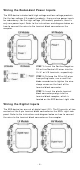
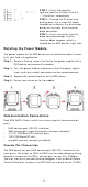
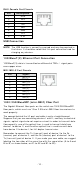
Table Of Contents
- EDS-G4014 Series Quick Installation Guide
- Package Checklist
- Default Settings
- Panel Views of EDS-G4014 Series
- Mounting Dimensions
- DIN-rail Mounting
- Wall Mounting (Optional)
- Wiring Requirements
- Grounding the Moxa EDS Series
- Suggested Wire Type for Wiring Relay Contact (RELAY), Digital Input (DI), and Power Inputs (P1/P2)
- Wiring the Relay Contact
- Wiring the Redundant Power Inputs
- Wiring the Digital Inputs
- Rotating the Power Module
- Communication Connections
- Reset Button
- Turbo Ring DIP Switch Settings
- LED Indicators
- Specifications

- 3 -
Bot t om Pa nel V ie w
1. m icroSD car d slot
(curr ent ly disabled)
2. Reset but t on
3.
DI P sw itches for Turbo
Ring, Ring Mast er, and
Ring Coupler
M ount in g D im e n sion s
DI N - rail M ount ing
The DI N- rail m ount ing kit is fixed to t he back panel of the EDS device
when you t ake it out of t he box. Mount t he EDS device on cor rosion -
fr ee m ount ing rails that m eet t he EN 60715 stan dar d.