
Installation Guide
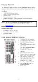
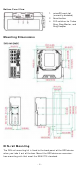
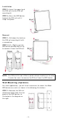
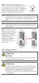
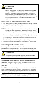
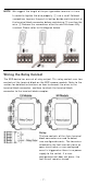
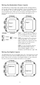
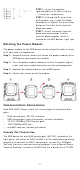
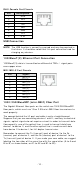
Table Of Contents
- EDS-G4014 Series Quick Installation Guide
- Package Checklist
- Default Settings
- Panel Views of EDS-G4014 Series
- Mounting Dimensions
- DIN-rail Mounting
- Wall Mounting (Optional)
- Wiring Requirements
- Grounding the Moxa EDS Series
- Suggested Wire Type for Wiring Relay Contact (RELAY), Digital Input (DI), and Power Inputs (P1/P2)
- Wiring the Relay Contact
- Wiring the Redundant Power Inputs
- Wiring the Digital Inputs
- Rotating the Power Module
- Communication Connections
- Reset Button
- Turbo Ring DIP Switch Settings
- LED Indicators
- Specifications

- 2 -
Pa cka ge Check list
The EDS- G4014 Ser ies indust rial DI N- rail EtherDevice Sw it ch ( EDS) is
shipped wit h t he following item s. I f any of t hese it em s are m issing or
dam aged, please cont act your custom er service represent ative for
assist an ce.
• 1 EDS- G4014 Ethernet sw itch
• Quick inst allat ion guide ( print ed)
• Warr ant y car d
• Subst ance disclosure t able
• Product cer tificate of quality inspect ion ( Sim plified Chinese)
• Product not ices ( Sim plified Chinese)
N OTE
You can find inform at ion and soft w ar e downloads on the
relevant product pages locat ed on Moxa’s w ebsite:
www .m oxa.com
De fault Se t t ings
• I P address: 192.168.1 27.253
• Subnet Mask : 255.255.255.0
• Usern am e: adm in
• Passw or d: m oxa
Pa n el Vie w s of EDS- G4 0 1 4 Se r ie s
1. 1000BaseT( X) LED indicat or
2. 10/ 100BaseT( X) LED in dicat or
3. 10/ 100/ 1000BaseT(X) port s,
Port 1 t o 8
4. 1000/ 2500BaseSFP port s, Port
QG1 t o QG2
100/ 1000/ 2500BaseSFP port s,
Port QG3 t o QG6
5. 1000/ 2500BaseSFP LED
indicator
6. Grounding connect or screw
7.
Ter m inal block s for power in put,
digital input , and relay out put
8. LED indicator s: STATE (S),
FAULT ( F), PWR1 ( P1) , PWR2
( P2), MSTR/ HEAD ( M/ H),
CPLR/ TAI L ( C/ T) , SYNC
9. Console por t ( RJ45, RS- 232)
10.
USB st orage port (t ype A,
current ly disabled)
11. Model nam e