
Installation Guide
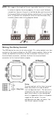
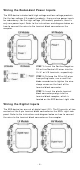
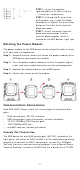
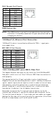
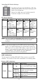

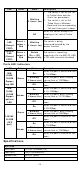
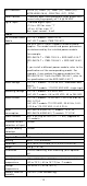
Table Of Contents
- EDS-G4014 Series Quick Installation Guide
- Package Checklist
- Default Settings
- Panel Views of EDS-G4014 Series
- Mounting Dimensions
- DIN-rail Mounting
- Wall Mounting (Optional)
- Wiring Requirements
- Grounding the Moxa EDS Series
- Suggested Wire Type for Wiring Relay Contact (RELAY), Digital Input (DI), and Power Inputs (P1/P2)
- Wiring the Relay Contact
- Wiring the Redundant Power Inputs
- Wiring the Digital Inputs
- Rotating the Power Module
- Communication Connections
- Reset Button
- Turbo Ring DIP Switch Settings
- LED Indicators
- Specifications

- 16 -
Altitude
Up to 2000 m
Note: Please cont act Moxa if y ou r equir e product s
guar ant eed t o funct ion pr operly at higher alt it ude.
Re gula tor y App rova ls
I ndust rial
Cybersecurit y
I EC 62443- 4-1 , I EC 62443- 4- 2
Safet y
UL 61010- 2- 201, EN 62368- 1( LVD)
EMC
EN 55022 / 24, EN 61000- 6- 2/ 6 - 4
EMI
FCC Par t 15 Subpar t B Class A
EMS EN 61000 -4 -2 ( ESD) Level 4
EN 61000 -4- 3 (RS) Level 3
EN 61000- 4- 4 ( EFT) Level 4
EN 61000 -4 -5 ( Sur ge) Level 4
EN 61000 -4 -6 ( CS) Level 3
EN 61000 -4 -8 Level 4
Shock
I EC 60068- 2-27
Free Fall
I EC 60068- 2-32
Vibration
I EC 60068- 2-6
Rail Traffic
( Way side)
EN 50121 -4
Tr affic Cont rol
NEMA TS2
W a rr an t y
Warrant y
5 years
ATTEN TI ON
This device com plies with Part 15 of t he FCC rules.
Operat ion is subject t o t he following conditions:
1. This device m ay not cause harm ful inter fer ence.
2. This device m ust accept any int erference received
including inter fer ence that m ay cause undesired operat ion.