
Installation Guide
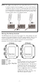
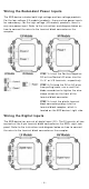
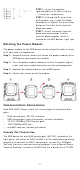
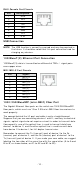
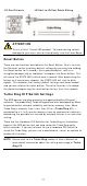
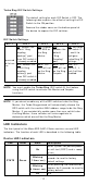

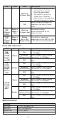
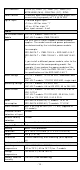
Table Of Contents
- EDS-G4014 Series Quick Installation Guide
- Package Checklist
- Default Settings
- Panel Views of EDS-G4014 Series
- Mounting Dimensions
- DIN-rail Mounting
- Wall Mounting (Optional)
- Wiring Requirements
- Grounding the Moxa EDS Series
- Suggested Wire Type for Wiring Relay Contact (RELAY), Digital Input (DI), and Power Inputs (P1/P2)
- Wiring the Relay Contact
- Wiring the Redundant Power Inputs
- Wiring the Digital Inputs
- Rotating the Power Module
- Communication Connections
- Reset Button
- Turbo Ring DIP Switch Settings
- LED Indicators
- Specifications

- 13 -
LED
Color
St a t e
De scr ip tion
Re d On
The syst em has initially failed
the boot - up process
• Sy st em I nfo. Read Fail or
EEPROM inform at ion err or
FAULT Re d
On
1.
The relay cont act has been
t riggered
2. The ingress rat e lim it has
been exceeded and the port
has entered shut down
m ode
3. I nvalid Rin g por t connect ion
Of f
When t he syst em boot s up and
runs corr ect ly or a user -
configured event is not
t riggered.
P1 Am b er
On
Power is being supplied t o power
input PWR.
Of f
Power is not being su pplied t o
power input PWR.
P2 Am b er
On
Power is being supplied t o power
input PWR.
Of f
Power is not being su pplied t o
power input PWR.
M STR/
HEAD
( M/ H)
Gr ee n
On
When t he sw it ch is
Mast er / Head/ Root of Tur bo
Ring/ Turbo Chain/ Fast RSTP.
Blin k ing
( 4 t im e s/ sec)
1. The switch has becom e the
Mast er of Turbo Ring after
Turbo Ring has gone down
2. The sw it ch is set as Head of
Turbo Chain and Turbo
Chain has gone down
3. The switch is set as the
Turbo Ring’s Mem ber and
t he corresponding Ring por t
is dow n
4. The switch is set as the
Turbo Chain’s Mem ber/ Tail
and the corr espon ding
Head- end Chain port is
down.
Of f
When t he sw itch is not t he
Mast er / Head/ Root of t his Turbo
Rin g/ Turbo Chain/ Fast RSTP.
CPLR/
TAI L
Gr ee n On
1. The switch’s ring coupling or
dual hom ing function is
enabled.
2. The switch is set as the Tail
of Tur bo Chain.