
Installation Guide
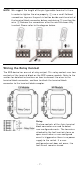
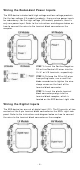
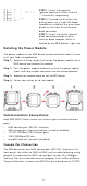
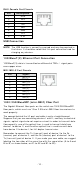
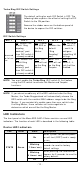

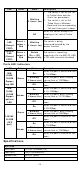
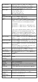
Table Of Contents
- EDS-G4014 Series Quick Installation Guide
- Package Checklist
- Default Settings
- Panel Views of EDS-G4014 Series
- Mounting Dimensions
- DIN-rail Mounting
- Wall Mounting (Optional)
- Wiring Requirements
- Grounding the Moxa EDS Series
- Suggested Wire Type for Wiring Relay Contact (RELAY), Digital Input (DI), and Power Inputs (P1/P2)
- Wiring the Relay Contact
- Wiring the Redundant Power Inputs
- Wiring the Digital Inputs
- Rotating the Power Module
- Communication Connections
- Reset Button
- Turbo Ring DIP Switch Settings
- LED Indicators
- Specifications

- 12 -
Turbo Ring D I P Sw itch Se t t ings
The default
set ting for each DI P Sw it ch is OFF. The
follow ing t able explains t he effect of set ting t he DI P
Sw it ch to t he ON posit ion
.
Rem ove t he rubber cover on t he bottom panel of
the device
t o expose t he DI P switches.
DI P Sw it ch Se t t ing s
DI P 1
DI P 2
DI P 3
DI P 4
DI P 5
Reserved
for fut ur e
use
ON :
Enables the
default “ Ring
Coupling
( backup) ” port
when DI P switch 4
is already enabled.
ON :
Enables
this EDS as
the Ring
Mast er .
ON :
Enables t he
default
“ Ring
Coupling”
port .
ON :
Act ivat es
DI P sw it ch 2,
3, and 4 to
configu re
Turbo Ring V2
set t ings.
OFF:
Enables t he
default Ring
Coupling
(prim ary) por t
when DI P switch 4
is already enabled.
OFF:
This
EDS will not
be the Rin g
Mast er .
OFF:
This
EDS will not
be the Rin g
Coupler .
OFF:
DI P
sw it ch 2, 3,
and 4 w ill be
disabled.
N OTE
You m ust enable the
Turbo Ring ( DI P sw it ch 5) fir st before
using the DI P sw it ch t o act ivat e the Mast er and Coupler
funct ions.
N OTE
I f you do not enable any of t
he EDS sw it ches t o be t he Ring
Mast er , t he Turbo Ring prot ocol will
aut om at ically choose t he
EDS swit ch
w it h the sm allest MAC address range t o b
e t he Rin g
Mast er . I f you accident ally enable m ore
than one sw it ch to be
the Ring Master , these switches will auto
-negot iat e to
det er m ine w hich one will be t he Ring Mast er.
LED I ndica t or s
The fr ont panel of t he Moxa EDS- G4014 Ser ies contains sever al LED
indicat ors. The funct ion of each LED is described in t he following table:
D evice LED I ndica t ors
LED
Color
St a t e
De scr ip tion
STATE Gr ee n
On
When syst em has passed pow er-
on self-t est ( POST) and is ready
to r un.
Blin k ing
( 1 t im e / se c)
Press the reset but ton for five
secon ds t o r eset t o fact ory
default set tings
Blin k ing
( 4 t im e s/ se c)
When pressing t he reset but ton
depress for 5 secon ds t o r eset t o
fact ory default.
Of f
N/ A