
Installation Guide

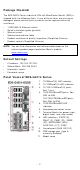
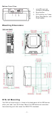
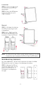
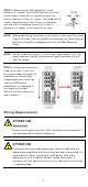
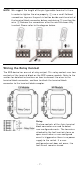
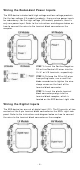
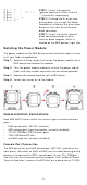
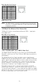
Table Of Contents
- EDS-G4014 Series Quick Installation Guide
- Package Checklist
- Default Settings
- Panel Views of EDS-G4014 Series
- Mounting Dimensions
- DIN-rail Mounting
- Wall Mounting (Optional)
- Wiring Requirements
- Grounding the Moxa EDS Series
- Suggested Wire Type for Wiring Relay Contact (RELAY), Digital Input (DI), and Power Inputs (P1/P2)
- Wiring the Relay Contact
- Wiring the Redundant Power Inputs
- Wiring the Digital Inputs
- Rotating the Power Module
- Communication Connections
- Reset Button
- Turbo Ring DIP Switch Settings
- LED Indicators
- Specifications

- 10 -
RJ4 5 Console Port Pin out s
Pin
De scr ip tion
1
DSR
2
RTS
3
–
4
TxD
5
RxD
6
GND
7
CTS
8
DTR
USB Conn e ct ion
N OTE
The USB funct ion is current ly reser ved and m ay be required in
the fut ure. I t should be not ed t hat this port cannot be used for
charging an y devices.
1 0 0 0 Base T( X) Et h ern et Port Connect ion
1000BaseT( X) data is t ransm it t ed on differ ential TRD+ / - signal pairs
over copper w ires.
MDI / M DI - X Port Pino ut s
Pin
Sign al
1
TRD( 0) +
2
TRD( 0) -
3
TRD( 1) +
4
TRD( 2) +
5
TRD( 2) -
6
TRD( 1) -
7
TRD( 3) +
8
TRD( 3) -
1 0 0 0 / 2 5 0 0 BaseSFP ( m in i- GBI C) Fiber Por t
The Gigabit Ether net fiber por ts on t he switch ar e 1000/ 2500BaseSFP
fiber port s, w hich m ust use 1 G or 2.5G m ini- GBI C fiber t ransceivers to
work pr operly.
The concept behind the LC port and cable is quit e st raightforw ard.
Suppose t hat you ar e connect ing devices I and I I ; contr ary t o elect r ical
signals, opt ical signals do not require a circuit in or der to t ransm it dat a.
Consequently, one of t he opt ical lines is u sed t o t ransm it dat a from
device I t o device I I , and t he ot her opt ical line is used t ransm it dat a
from device I I t o device I , for full- duplex t r ansm ission.
Rem em ber t o connect t he Tx ( t ransm it ) port of device I to t he Rx
(receive) port of device I I , and the Rx ( receive) port of device I to the
Tx ( t ransm it ) por t of device I I . I f you m ak e you r own cable, w e su ggest
labeling the t wo sides of t he sam e line with t he sam e let t er (A- to- A and
B- t o-B, as shown below , or A1- to- A2 and B1- t o- B2) .