ED S- G4 0 1 4 Se rie s Quick I nst a lla t ion Guide M ox a Et he r D e vice ™ Sw it ch Ve r sion 1 .0 , M a r ch 2 0 2 2 Te chnica l Suppor t Con t a ct I nfor m a t ion w w w .m ox a . com / suppor t 2022 Moxa I nc. All right s reserv ed.
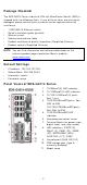
Pa ck a ge Che ck list The EDS- G4014 Series indust rial DI N- rail Et herDevice Sw it ch ( EDS) is shipped w it h t he follow ing it em s. I f any of t hese it em s are m issing or dam aged, please cont act y our cust om er service represent at ive for assist ance.
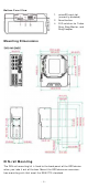
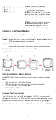
Bot t om Pa ne l Vie w 1. 2. 3. m icroSD card slot ( current ly disabled) Reset but t on DI P sw it ches for Turbo Ring, Ring Mast er, and Ring Coupler M oun t ing D im e n sion s D I N - r a il M ount ing The DI N- rail m ount ing k it is fixed t o t he back panel of t he EDS device w hen you t ake it out of t he box. Mount t he EDS device on corrosionfree m ount ing rails t hat m eet t he EN 60715 st andard.
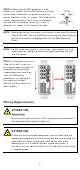
I nst a lla t ion STEP 1 —I nsert t he upper lip of t he DI N rail int o t he DI N- rail m ount ing kit . STEP 2 —Press t he EDS device t ow ards t he DI N rail unt il it snaps int o place. Re m ova l STEP 1 —Pull dow n t he lat ch on t he DI N- rail m ount ing kit w it h a screw driver. STEP 2 & 3 —Slight ly pull t he EDS device forw ard and lift up t o rem ove it from t he DI N rail.
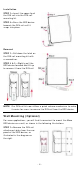
STEP 2 —Mount ing t he EDS device on a w all requires six screw s. Use t he EDS device, w it h w all m ount plat es at t ached, as a guide t o m ar k t he correct locat ions of t he six screw s. The heads of t he screw s should be less t han 6.0 m m in diam et er, and t he shaft s should be less t han 3.5 m m in diam et er, as show n in t he figure on at right .
ATTEN TI ON Sa fe t y Fir st ! Be sure t o disconnect t he pow er cord before inst alling and/ or w iring your EDS device. Calculat e t he m axim um possible current in each pow er w ire and com m on w ire. Observe all elect rical codes dict at ing t he m axim um current allow able for each w ire size. I f t he current goes above t he m axim um rat ings, t he w iring could overheat , causing serious dam age t o your equipm ent .
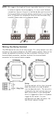
N OTE We suggest t he lengt h of t he pin t ype cable t er m inal is 8 m m . I n order t o t ight en t he w ire proper ly, ① use a sm all flat head screw driver t o press t he push - in but t on beside each t er m inal of t he t erm inal block connect or befor e and during ② insert ing t he w ire. ③ Release t he screw driver aft er t he w ire has been fully insert ed. Please refer t o t he diagram below . W ir ing t he Re la y Cont a ct The EDS device has one set of relay out put .
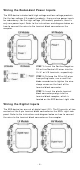
W ir ing t he Re dunda nt Pow e r I n put s The EDS device includes bot h high- volt age and low - volt age pr oduct s. For t he low - volt age ( LV m odels) product s, t here are t w o pow er input s for redundancy ; for t he high - volt age ( HV m odels) pr oduct s, t here is only one pow er input . Refer t o t he inst ruct ions and diagram below on how t o connect t he w ires t o t he t erm inal block connect or on t he recept or.
STEP 1 : I nsert t he negat ive ( ground) / posit ive DI w ires int o t he ┴/ I t erm inals, respect ively. STEP 2 : To keep t he DI w ires from pulling loose, use a sm all flat - blade screw driver t o t ight en t he w ire- clam p but t on on t he front of t he t erm inal block connect or. STEP 3 : I nsert t he plast ic t erm inal block connect or prongs int o t he t erm inal block recept or, w hich is locat ed on t he EDS devices’ right side.
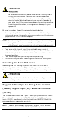
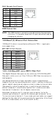
RJ4 5 Console Por t Pinou t s Pin 1 2 3 4 5 6 7 8 D e scr ipt ion DSR RTS – TxD RxD GND CTS DTR USB Conn e ct ion N OTE The USB funct ion is current ly reserved and m ay be required in t he fut ure. I t should be not ed t hat t his port cannot be used for charging any devices. 1 0 0 0 Ba se T( X) Et h e r n et Por t Conn e ct ion 1000BaseT( X) dat a is t ransm it t ed on different ial TRD+ / - signal pair s over copper w ires.
LC- Por t Pinout s LC- Por t t o LC- Por t Ca ble W ir in g ATTEN TI ON This is a Class 1 Laser/ LED product . To av oid causing serious dam age t o y our eyes, do not st are direct ly int o t he Laser Beam . Re se t But t on There are t w o funct ions available on t he Reset But t on. One is t o reset t he Et hernet sw it ch t o fact ory default set t ings by pressing and holding t he Reset but t on for 5 seconds.
Tur bo Ring D I P Sw it ch Se t t ings The default set t ing for each DI P Sw it ch is OFF. The follow ing t able explains t he effect of set t ing t he DI P Sw it ch t o t he ON posit ion. Rem ove t he rubber cover on t he bot t om panel of t he device t o expose t he DI P sw it ches. D I P Sw it ch Se t t ings DI P 1 DI P 2 ON : Enables t he default “ Ring Coupling ( backup) ” port w hen DI P sw it ch 4 Reserved is already enabled.
LED Color Re d FAULT Re d P1 Am be r P2 Am be r M STR/ H EAD ( M/ H) Gr e e n CPLR/ TAI L Gr e e n St a t e D e scr ipt ion The syst em has init ially failed t he boot - up process On • Syst em I nfo. Read Fail or EEPROM infor m at ion error 1. The relay cont act has been t riggered 2. The ingress rat e lim it has been exceeded and t he port On has ent ered shut dow n m ode 3.
LED Syst e m LED ( Ex ce pt PW R) Syst e m LED ( Ex ce pt PW R) Color St a t e D e scr ipt ion 1. The sw it ch is set as t he Tail of Tur bo Chain and t he Chain has gone dow n. Blink ing 2. The sw it ch is set as t he ( 4 t im e s/ se c) Turbo Chain’s Mem ber/ Head and t he corresponding Tail- end Chain port is dow n. When t he sw it ch disables t he Off coupling or t ail r ole of Turbo Chain.
LED I ndicat or s Alarm Cont act Digit al I nput STATE ( S) , FAULT ( F) , PWR1 ( P1) , PWR2 ( P2) , MSTR/ HEAD ( M/ H) , CPLR/ TAI L ( C/ T) , SYNC 1 nor m ally open elect rom agnet ic r elay out put w it h current carrying capacit y of 1 A @ 24 VDC 1 isolat ed digit al input : + 13 t o + 30V for st at e “ 1” - 30 t o + 3V for st at e “ 0” Max.
Alt it ude Up t o 2000 m Not e: Please cont act Moxa if y ou r equire product s guarant eed t o funct ion pr operly at higher alt it ude.