
Installation Guide
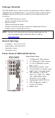
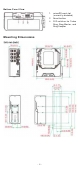
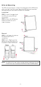
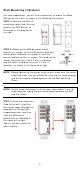
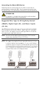
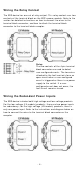
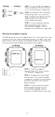
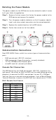
Table Of Contents
- EDS-G4008 Series Quick Installation Guide
- Package Checklist
- Default Settings
- Panel Views of EDS-G4008 Series
- Mounting Dimensions
- DIN-rail Mounting
- Wall Mounting (Optional)
- Wiring Requirements
- Grounding the Moxa EDS Series
- Suggested Wire Type for Wiring Relay Contact (RELAY), Digital Input (DI), and Power Inputs (P1/P2)
- Wiring the Relay Contact
- Wiring the Redundant Power Inputs
- Wiring the Digital Inputs
- Rotating the Power Module
- Communication Connections
- Reset Button
- Turbo Ring DIP Switch Settings
- LED Indicators
- Specifications

- 9 -
STEP 1 : I nser t t he Posit ive/ Negat ive
DC or Line/ Neut ral AC w ires
int o t he
V+ / V
- or L/ N t er m inals, r espect ively.
STEP 2 :
To keep t he DC or AC wires
fr om pulling loose, use a sm all flat
-
blade scr ew dr iver t o t ight en t he wire
-
clam p screw s on t he front of t he
t erm inal block connect or.
STEP 3 :
I nser t t he plast ic term inal
bloc
k connect or pron gs int o t he
ter m inal block recept or, w hich is
locat ed on t he EDS devices’ right side.
W irin g t he Digit a l I nput s
The EDS device has one set of digit al input (DI ) . The DI consist s of t wo
con tact s of t he 4- pin term inal block connector on the EDS's right - side
panel. Refer t o t he instruct ions an d diagram below on how t o connect
the w ires t o the ter m inal block connect or on t he receptor.
STEP 1 :
I nser t t he negat ive
(ground) / posit ive DI wires int o th e
┴
/ I t erm inals, respect ively.
STEP 2 :
To keep t he DI w ires fr om
pulling loose, use a sm all flat
-blade
scr ew dr iver t o t ight en the wir e
-clam p
but t on
on t he front of t he t erm inal
block connect or .
STEP 3 :
I nser t t he plast ic term inal
block connect or pron gs int o t he
ter m inal block recept or, w hich is
locat ed on t he EDS devices’ r ight side.