
Installation Guide
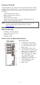
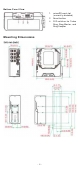
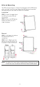
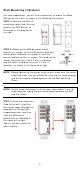
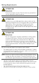
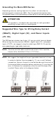
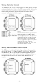
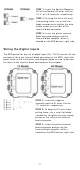
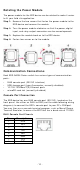
Table Of Contents
- EDS-G4008 Series Quick Installation Guide
- Package Checklist
- Default Settings
- Panel Views of EDS-G4008 Series
- Mounting Dimensions
- DIN-rail Mounting
- Wall Mounting (Optional)
- Wiring Requirements
- Grounding the Moxa EDS Series
- Suggested Wire Type for Wiring Relay Contact (RELAY), Digital Input (DI), and Power Inputs (P1/P2)
- Wiring the Relay Contact
- Wiring the Redundant Power Inputs
- Wiring the Digital Inputs
- Rotating the Power Module
- Communication Connections
- Reset Button
- Turbo Ring DIP Switch Settings
- LED Indicators
- Specifications

- 8 -
W irin g t he Re lay Con t a ct
The EDS device has one set of relay out put . This relay cont act uses t wo
cont act s of t he t erm inal block on the EDS’s power m odule. Refer t o t he
sect ion for det ailed inst ruct ions on how t o connect t he wires t o t he
term inal block connect or , and how to att ach t he term inal block
connect or t o t he t erm inal block r ecept or.
Re la y:
The t wo cont act s of
the 4 -pin t erm inal
block connector are used to det ect
user
-configured event s. The t wo w ires
at tached t o the
fault cont act s for m an
open cir cu i
t w hen a user -configured
event is triggered or
there is no pow er
supply t o t he sw it ch
. I f a u ser-
configured event does not oc
cur, t he
fault cir cu it rem ains closed.
W irin g t he Re dunda nt Pow e r I nput s
The EDS device includes both high - volt age and low - volt age pr oduct s.
For t he low- volt age ( LV models) pr oduct s, t here are t wo power input s
for r edundancy ; for t he high- volt age ( HV m odels) pr oduct s, t here is
only one pow er input . Refer t o t he inst ruct ion s and diagram below on
how t o connect t he w ires t o the t erm inal block connect or on the
recept or.