
Installation Guide
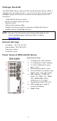
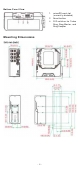
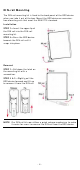
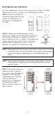
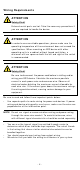
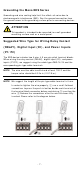
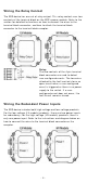
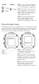
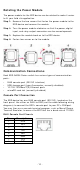
Table Of Contents
- EDS-G4008 Series Quick Installation Guide
- Package Checklist
- Default Settings
- Panel Views of EDS-G4008 Series
- Mounting Dimensions
- DIN-rail Mounting
- Wall Mounting (Optional)
- Wiring Requirements
- Grounding the Moxa EDS Series
- Suggested Wire Type for Wiring Relay Contact (RELAY), Digital Input (DI), and Power Inputs (P1/P2)
- Wiring the Relay Contact
- Wiring the Redundant Power Inputs
- Wiring the Digital Inputs
- Rotating the Power Module
- Communication Connections
- Reset Button
- Turbo Ring DIP Switch Settings
- LED Indicators
- Specifications

- 7 -
Gr ounding t he M oxa ED S Se ries
Grounding and wire rout ing help lim it t he effect s of noise due t o
electr om agnet ic int erference (EMI ). Run the ground connect ion from
the ground screw t o t he grounding surface pr ior t o connecting devices.
ATTEN TI ON
This product is int ended t o be m ount ed t o a well
-gr ounded
m ounting surface such as a met al panel.
Sug ge st ed W ire Type f or W ir ing Relay Con t a ct
( RELAY) , Digit a l I nput ( D I ) , a nd Pow e r I n put s
( P1 / P2 )
The EDS device includes t wo 4-pins 3.5 m m pin-pit ch t er m in al block s.
When w iring t he r elay cont act ( RELAY), digit al input (DI ) , and pow er
inputs ( P1/ P2) , w e suggest using t he cable t ype AWG 18- 24 and t he
cor responding pin t ype cable term inals.
N OTE
The wir e m ust be
able t o wit hst and at least 105 ° C and t he
torque value should be 4.5 lb- in ( 0.51 N- m ) .
N OTE
We suggest t he length of t he pin t ype cable t er m inal is 8 m m .
I n order t o tight en t he wire proper ly,
① use a sm all flathead
screwdriver t o press t he push
-
in but ton beside each t er m inal of
the t erm inal block connect or befor e and durin g
②
inser ting t he
wire.
③ Release t he screwdriver after the wir e has been fully
insert ed. Please refer t o t he diagram
below.