
Installation Guide
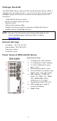
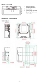
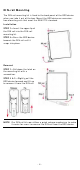
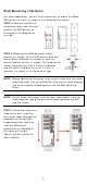
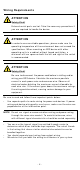
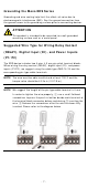
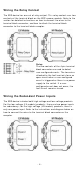
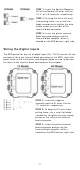
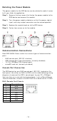
Table Of Contents
- EDS-G4008 Series Quick Installation Guide
- Package Checklist
- Default Settings
- Panel Views of EDS-G4008 Series
- Mounting Dimensions
- DIN-rail Mounting
- Wall Mounting (Optional)
- Wiring Requirements
- Grounding the Moxa EDS Series
- Suggested Wire Type for Wiring Relay Contact (RELAY), Digital Input (DI), and Power Inputs (P1/P2)
- Wiring the Relay Contact
- Wiring the Redundant Power Inputs
- Wiring the Digital Inputs
- Rotating the Power Module
- Communication Connections
- Reset Button
- Turbo Ring DIP Switch Settings
- LED Indicators
- Specifications

- 4 -
DI N - r a il M ou nt ing
The DI N- rail m ount ing k it is fixed to t he back panel of t he EDS device
when you t ake it out of t he box. Mount t he EDS device on cor rosion -
fr ee m ount ing rails that m eet t he EN 60715 stan dar d.
I nst allat ion
STEP 1 —I nser t t he upper lip of
the DI N r
ail int o t he DI N- rail
m ounting kit.
STEP 2
—Press t he EDS device
towar ds t he
DI N rail unt il it
snaps into place.
Re m ov al
STEP 1
—
Pull down t he lat ch on
the m ount ing kit w it h a
scr ew dr iver.
STEP 2
& 3 —Slightly pull the
EDS device for war d and lift up
to r em ove it from the DI N rail.
N OTE
Our DI N r ail
kit
now utilizes a quick release m echanism to m ake
it easier for user s t o rem ove the DI N rail from t he EDS device.