
Installation Guide
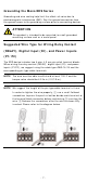
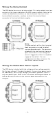
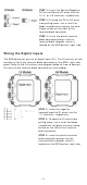
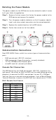
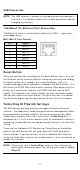
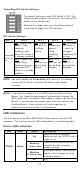
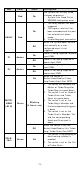
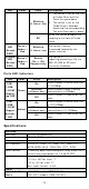
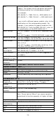
Table Of Contents
- EDS-G4008 Series Quick Installation Guide
- Package Checklist
- Default Settings
- Panel Views of EDS-G4008 Series
- Mounting Dimensions
- DIN-rail Mounting
- Wall Mounting (Optional)
- Wiring Requirements
- Grounding the Moxa EDS Series
- Suggested Wire Type for Wiring Relay Contact (RELAY), Digital Input (DI), and Power Inputs (P1/P2)
- Wiring the Relay Contact
- Wiring the Redundant Power Inputs
- Wiring the Digital Inputs
- Rotating the Power Module
- Communication Connections
- Reset Button
- Turbo Ring DIP Switch Settings
- LED Indicators
- Specifications

- 14 -
LED
Color
St a t e
De scr ip tion
Blin k ing
( 4 t im e s/ se c)
1. The switch is set as the Tail
of Tur bo Chain and the
Chain has gone down.
2. The switch is set as the
Turbo Chain’s Member/
Head and t he cor responding
Tail-end Chain port is down.
Of f
When the swit ch disables t he
coupling or t ail role of Tur bo
Chain.
Syst e m
LED
( Except
PW R)
Gree n +
Am b er +
Re d
Blin k ing
( 2 t im e s/ se c)
The switch is being
discover ed/ located by the
locat or funct ion.
Syst e m
LED
( Except
PW R)
Gree n +
Am b er +
Re d
Rot a t e
On - > Off
Seq ue ntia lly
The switch is
im por ting/ ex port ing a file via
ABC-02- USB or SD car d
(curr ent ly disabled) .
Por t s LED I ndicat or s
LED
Color
St a t e
De scr ip tion
1 0 M /
1 0 0 M /
1 0 0 0 M
Copper
t op LED
Gr ee n
On
When the port is act ive and link s
at 1000Mbps.
Blin k ing
( 4 t im e s/ se c)
When the port ’s dat a is being
tr ansm itt ed at 1000Mbps.
Of f
When t he port is inact ive or link
down.
1 0 M /
1 0 0 M /
1 0 0 0 M
Copper
bot t om
LED
Am b er
On
When the port is act ive and link s
at 10/ 100 Mbps.
Blin k ing
( 4 t im e s/ se c)
When the port ’s dat a is being
tr ansm itt ed at 10/ 100Mbps.
Of f
When t he port is inact ive or link
down.
Spe cificat ions
I nt e r fa ce
RJ45 Port s
10/ 100/ 1000BaseT( X)
Console Por t
RS-232 ( RJ45 )
But t on
Reset but t on
LED I ndicat or s STATE (S), FAULT ( F), PWR1 ( P1) , PWR2 ( P2) ,
MSTR/ HEAD ( M/ H), CPLR/ TAI L ( C/ T) , SYNC
Alarm Cont act
1 nor m ally open elect rom agnet ic relay out put with
curr ent carr ying capacit y of 1 A @ 24 VDC
Digit al I nput
1 isolat ed digit al input:
+ 13 t o + 30V for st at e “ 1”
-30 t o + 3V for state “ 0”
Max. in put cur rent : 8 m A
Pow e r
Pre- inst alled Power
Module
-LV/ -LV- T m odels: PWR- 100–LV
-HV/ -HV- T m odels: PWR- 105-HV-I