
Installation Guide
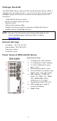
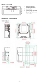
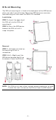
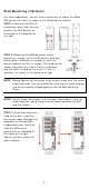
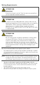
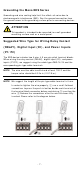
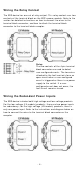
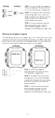
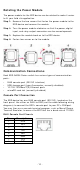
Table Of Contents
- EDS-G4008 Series Quick Installation Guide
- Package Checklist
- Default Settings
- Panel Views of EDS-G4008 Series
- Mounting Dimensions
- DIN-rail Mounting
- Wall Mounting (Optional)
- Wiring Requirements
- Grounding the Moxa EDS Series
- Suggested Wire Type for Wiring Relay Contact (RELAY), Digital Input (DI), and Power Inputs (P1/P2)
- Wiring the Relay Contact
- Wiring the Redundant Power Inputs
- Wiring the Digital Inputs
- Rotating the Power Module
- Communication Connections
- Reset Button
- Turbo Ring DIP Switch Settings
- LED Indicators
- Specifications

- 10 -
Rot a t ing t h e Pow er Module
The power m odule for t he EDS device can be rot at ed t o m ake it easier
to fit y our field site applicat ion.
St ep 1 :
Rem ove the t w o screws t hat fast en t he pow er m odule t o the
EDS device
and r em ov e the m odule.
St ep 2 :
Turn the power m odule clockw ise so that t he power , digit al
input
, and r elay out put connect ors can be m oved u pw ar ds.
St ep 3 :
Repl
ace t he m odule back on t o t he EDS device.
St ep 4 :
Fast en t w o screws on t o t he m odule.
Com m unica t ion Connect ion s
Each EDS- G4008 Series sw it ch has various t ypes of com m unicat ion
port s:
• RJ45 console port ( RS-232 int erface)
• USB st orage port ( t ype A connect or , cur ren tly disabled)
• 10/ 100/ 1000BaseT( X) Et hernet port s
• m icroSD car d slot ( curr ent ly disabled)
Con sole Port Con n e ct ion
The EDS dev ice has one RJ45 console por t ( RS-23 2), locat ed on t he
front panel. Use eit her an RJ45- t o- DB9 ( see t he cable follow ing wiring
diagr am s) t o connect t he EDS’s console por t t o your PC’s COM port .
You m ay t hen use a console ter m inal program , such as Moxa PCom m
Ter m inal Em ulat or , t o access t he EDS that has a baud rat e of 1152 00.
RJ4 5 Console Port Pin ou t s
Pin
De scr ip tion
1
DSR
2
RTS
3
–
4
TxD
5
RxD
6
GND
7
CTS
8
DTR