EDS-G205A-4PoE Hardware Installation Guide Moxa EtherDevice Switch First Edition, October 2011 2011 Moxa Inc. All rights reserved.
Overview The EDS-G205A-4PoE series industrial Ethernet switches are rugged entry-level industrial 5-port gigabit PoE switches that support IEEE 802.3, IEEE 802.3u, IEEE 802.3x with 10/100/1000M, full/half-duplex, MDI/MDIX auto-sensing, and IEEE 802.3af/IEEE 802.3at PoE standards. The EDS-G205A-4PoE series provides 24/48 VDC redundant power inputs that can be connected simultaneously to a live DC power source.
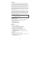
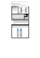
EDS-G205A-4PoE (Standard) Panel Layouts 1. 2. 3. 4. 5. 6. 7. 8. 9. 10. 11. 12. 13. 14. 15.
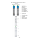
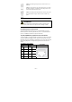
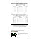
Mounting Dimensions (unit = mm) DIN-Rail Mounting The aluminum DIN-Rail attachment plate should already be fixed to the back panel of the EDS when you take it out of the box. If you need to reattach the DIN-Rail attachment plate, make sure the stiff metal spring is situated towards the top, as shown in the figures below. STEP 1: STEP 2: Insert the top of the DIN-Rail into The DIN-Rail attachment unit will the slot just below the stiff metal snap into place as shown below. spring.
To remove the EDS from the DIN-Rail, simply reverse Steps 1 and 2 above. Wall Mounting (optional) For some applications, you will find it convenient to mount the EDS-G205A-4PoE on the wall, as shown in the following figures. STEP 1: Remove the aluminum DIN-Rail attachment plate from the EDS-G205A-4PoE’s rear panel, and then attach the wall mount plates as shown in the diagram at the right. STEP 2: Mounting the EDS-G205A-4PoE on the wall requires 4 screws.
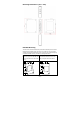
Wiring Requirements WARNING Safety First Turn the power off before disconnecting modules or wires. The correct power supply voltage is listed on the product label. Check the voltage of your power source to make sure that you are using the correct voltage. Do NOT use a voltage greater than what is specified on the product label Calculate the maximum possible current in each power wire and common wire. Observe all electrical codes dictating the maximum current allowable for each wire size.
STEP 1: Insert the negative/positive DC wires into the V-/V+ terminals. STEP 2: To keep the DC wires from pulling loose, use a small flat-blade screwdriver to tighten the wire-clamp screws on the front of the terminal block connector. STEP 3: Insert the plastic terminal block connector prongs into the terminal block receptor, which is located on EDS’s top panel. ATTENTION Before connecting the EtherDevice Switch to the DC power inputs, make sure the DC power source voltage is stable.
1000Base-T Pinouts MDI Port Pinouts Pin Signal 1 BI_DA+ 2 BI_DA3 BI_DB+ 4 BI_DC+ 5 BI_DC6 BI_DB7 BI_DD+ 8 BI_DD- MDI-X Port Pinouts Pin Signal 1 BI_DB+ 2 BI_DB3 BI_DA+ 4 BI_DD+ 5 BI_DD6 BI_DA7 BI_DC+ 8 BI_DC- 8-pin RJ45 PoE Ethernet Port Connection PoE ports located on the EDS switch’s front panel are used to connect to PoE-enabled devices. The pinout follows the Alternative A, MDI mode” of 802.3af/802.3at standards. Please see the details in the following table.
RJ45 (8-pin) to RJ45 (8-pin) Cable Wiring NOTE If the PD only supports PoE MDI mode (V+, V+, V-, V- for pins 1, 2, 3, 6), choose a cross-over Ethernet cable to connect the PD and the EDS switch. If the PD only supports PoE MDI-X mode (V-, V-, V+, V+ for pins 1, 2, 3, 6), choose a straight-through Ethernet cable between the PD and the EDS switch. Redundant Power Inputs Both power inputs can be connected simultaneously to live DC power sources.
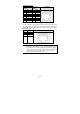
DIP Switch Setting Description – – Serves no function (reserved for future use). BSP ON Enables broadcast storm protection OFF Disables broadcast storm protection ATTENTION To actively update DIP switch settings, power off and then power on the EDS. LED Indicators The front panel of the EDS switches contain several LED indicators. The function of each LED is described in the following table.
Auto MDI/MDI-X Connection The Auto MDI/MDI-X function allows users to connect the EDS’s 10/100/1000Base-T(X) ports to any kind of Ethernet device, without needing to pay attention to the type of Ethernet cable being used for the connection. This means that you can use either a straight-through cable or cross-over cable to connect the EDS to Ethernet devices.
Specifications Technology Standards Processing Type Interface RJ45 Ports Fiber Ports LED Indicators DIP Switch Power Input Voltage Input Current IEEE 802.3 for 10BaseT, IEEE 802.3u for 100BaseT(X) and 100BaseFX, IEEE 802.3ab for 1000Base-T IEEE 802.3z for 1000Base-X IEEE 802.3x for Flow Control IEEE 802.3af for PoE IEEE 802.
Shock Freefall Vibration WARRANTY Time Period Details EN61000-4-5 (Surge), Level 3 EN61000-4-6 (CS), Level 3 EN61000-4-8 IEC 60068-2-27 IEC 60068-2-32 IEC 60068-2-6 5 years www.moxa.com/warranty Technical Support Contact Information www.moxa.