Communication Redundancy User’s Manual First Edition, March 2011 www.moxa.com/product © 2011 Moxa Inc. All rights reserved.
Communication Redundancy User’s Manual The software described in this manual is furnished under a license agreement and may be used only in accordance with the terms of that agreement. Copyright Notice © 2011 Moxa Inc., All rights reserved. Trademarks The MOXA logo is a registered trademark of Moxa Inc. All other trademarks or registered marks in this manual belong to their respective manufacturers.
Table of Contents 1. Introduction to Communication Redundancy .................................................................................... 1-1 2. Turbo Ring ........................................................................................................................................ 2-1 The Turbo Ring Concept ...................................................................................................................... 2-2 Setting up “Turbo Ring” or “Turbo Ring V2”...............
1 1. Introduction to Communication Redundancy Setting up Communication Redundancy on your network helps protect critical links against failure, protects against network loops, and keeps network downtime at a minimum. Communication Redundancy allows you to set up redundant loops in the network to provide a backup data transmission route in the event that a cable is inadvertently disconnected or damaged.
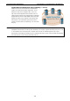
Communication Redundancy Introduction to Communication Redundancy Gigabit Ethernet Redundant Ring Capability (< 50 ms) Ethernet has become the default data communications medium for industrial automation applications. In fact, Ethernet is often used to integrate video, voice, and high-rate industrial application data transfers into one network. Moxa switches come equipped with a redundant Gigabit Ethernet protocol called Gigabit Turbo Ring.
2 2.
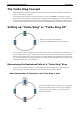
Communication Redundancy Turbo Ring The Turbo Ring Concept Moxa developed the proprietary Turbo Ring protocol to optimize communication redundancy and achieve a faster recovery time on the network. The Turbo Ring and Turbo Ring V2 protocols identify one switch as the master of the network, and then automatically block packets from traveling through any of the network’s redundant loops.
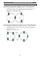
Communication Redundancy Turbo Ring When the Number of Switches in the Turbo Ring is Odd If there are 2N+1 switches (an odd number) in the “Turbo Ring” ring, with switches and segments labeled counterclockwise, then segment N+1 will serve as the backup path. For the example shown here, N=1, so that N+1=2. Determining the Redundant Path of a “Turbo Ring V2” Ring For a “Turbo Ring V2” ring, the backup segment is the segment connected to the 2nd redundant port on the master.
Communication Redundancy Turbo Ring Ring Coupling for a “Turbo Ring” Ring To configure the Ring Coupling function for a “Turbo Ring” ring, select two switches (e.g., Switch A and B in the above figure) in the ring, and another two switches in the adjacent ring (e.g., Switch C and D). Decide which two ports in each switch are appropriate to be used as coupling ports, and then link them together. Next, assign one switch (e.g.
Communication Redundancy NOTE Turbo Ring You do not need to use the same switch for both Ring Coupling and Ring Master. Dual-Ring Configuration (applies only to “Turbo Ring V2”) The dual-ring option provides another ring coupling configuration, in which two adjacent rings share one switch. This type of configuration is ideal for applications that have inherent cabling difficulties.
Communication Redundancy Turbo Ring Configuring “Turbo Ring” and “Turbo Ring V2” Use the Communication Redundancy page to select Turbo Ring, Turbo Ring V2, or Turbo Chain. Note that configuration pages for these three protocols are different. Configuring “Turbo Ring” Explanation of “Current Status” Items Now Active It shows which communication protocol is in use: Turbo Ring, Turbo Ring V2, RSTP, or none. Master/Slave It indicates whether or not this switch is the Master of the Turbo Ring.
Communication Redundancy Turbo Ring Explanation of “Settings” Items Redundancy Protocol Setting Description Factory Default Turbo Ring Select this item to change to the Turbo Ring configuration page. Turbo Ring V2 Select this item to change to the Turbo Ring V2 configuration page. Turbo Chain Select this item to change to the Turbo Chain configuration page. RSTP (IEEE 802.1W/ 802.1D-2004) None None Select this item to change to the RSTP configuration page.
Communication Redundancy Turbo Ring Default Coupling Port Default Coupling Control Port The fourth from the last port The third from the last port EDS-518A Series Port 15 Port 16 EDS-510A Series Port 7 Port G1 EDS-608/616 The second port of the last module The first port of the last module EDS-611/619 Port G1 The last port of the last module EDS-728/828 Series Port 1-3 Port 1-4 EDS-400A Series EDS-505A/508A/516A Series IKS-6726 Series IKS-G6524/G6824 Series without Gigabit Ethernet mo
Communication Redundancy NOTE Turbo Ring The user does not need to set the master to use Turbo Ring. If master is not set, the Turbo Ring protocol will assign master status to one of the EDS units in the ring. The master is only used to determine which segment serves as the backup path.
Communication Redundancy Turbo Ring Default 1st Port Default 2nd Port The second from the last port The last port EDS-518A Series Port G1 Port G2 EDS-510A Series Port G2 Port G3 EDS-608/616 The third port of the last module The fourth port of the last module EDS-400A Series EDS-505A/508A/516A Series EDS-611/619 Port G2 Port G3 EDS-728/828 Series Port 1-1 Port 1-2 IKS-6726 Series without Gigabit Ethernet module: without Gigabit Ethernet module: Port 1-1 Port 1-2 with Gigabit Etherne
Communication Redundancy NOTE Turbo Ring The Turbo Ring DIP Switches located on the outer casing of EDS series switches can be used to configure the switches’ Turbo Ring protocols. If you use the web interface, console interface, or Telnet interface to enable the Turbo Ring DIP Switches, and then set DIP Switch 4 on the switch’s outer casing to the ON position, you will not be able to use the web interface, console interface, or Telnet interface to change the status of the DIP Switch.
3 3.
Communication Redundancy Turbo Chain The Turbo Chain Concept Moxa’s Turbo Chain is an advanced software-technology that gives network administrators the flexibility of constructing any type of redundant network topology. When using the “chain” concept, you first connect the Ethernet switches in a chain and then simply link the two ends of the chain to an Ethernet network, as illustrated in the following figure. Turbo Chain can be used on industrial networks that have a complex topology.
Communication Redundancy Turbo Chain Configuring “Turbo Chain” Head Switch Configuration Member Switch Configuration Tail Switch Configuration Explanation of “Current Status” Items Now Active It shows which communication protocol is in use: Turbo Ring, Turbo Ring V2, RSTP, Turbo Chain, or None. The “Ports Status” indicators show Forwarding for normal transmission, Blocked if this port is connected to the Tail port as a backup path and the path is blocked, and Link down if there is no connection.
Communication Redundancy Turbo Chain Explanation of “Settings” Items Redundancy Protocol Setting Description Factory Default Turbo Ring Select this item to change to the Turbo Ring configuration page. Turbo Ring V2 Select this item to change to the Turbo Ring V2 configuration page. Turbo Chain Select this item to change to the Turbo Chain configuration page RSTP Select this item to change to the RSTP configuration page.
Communication Redundancy Turbo Chain Member Role Default 1st Member Port Default 2nd Member Port EDS-400A Series The second from the last port The last port EDS-518A Series Port G1 Port G2 EDS-510A Series Port G2 Port G3 EDS-608/616 The third port of the last module The fourth port of the last module EDS-611/619 Port G2 Port G3 EDS-728/828 Series Port 1-1 Port 1-2 IKS-6726 Series without Gigabit Ethernet module: Port without Gigabit Ethernet module: Port 1-1 1-2 EDS-505A/508A Ser
4 4.
Communication Redundancy STP/RSTP/MSTP The STP/RSTP/MSTP Concept Spanning Tree Protocol (STP) was designed to help reduce link failures on a network, and provide provide an automatic means of avoiding loops. This is particularly important for networks that have a complicated architecture, since unintended loops in the network can cause broadcast storms. Moxa switches’ STP feature is disabled by default. To be completely effective, you must enable RSTP/STP on every Moxa switch connected to your network.
Communication Redundancy STP/RSTP/MSTP LAN 1 Bridge A Bridge B LAN 2 Bridge C LAN 3 What happens if a link failure is detected? As shown in next figure, the STP process reconfigures the network so that traffic from LAN segment 2 flows through bridge B. LAN 1 Bridge A Bridge B LAN 2 Bridge C LAN 3 STP will determine which path between each bridged segment is most efficient, and then assign a specific reference point on the network.
Communication Redundancy STP/RSTP/MSTP STP Calculation The first step of the STP process is to perform calculations. During this stage, each bridge on the network transmits BPDUs. The following items will be calculated: • Which bridge should be the Root Bridge. The Root Bridge is the central reference point from which the • The Root Path Costs for each bridge. This is the cost of the paths from each bridge to the Root Bridge. • The identity of each bridge’s Root Port.
Communication Redundancy STP/RSTP/MSTP STP Example The LAN shown in the following figure has three segments, with adjacent segments connected using two possible links. The various STP factors, such as Cost, Root Port, Designated Bridge Port, and Blocked Port are shown in the figure. • Bridge A has been selected as the Root Bridge, since it was determined to have the lowest Bridge Identifier on the network. • Since Bridge A is the Root Bridge, it is also the Designated Bridge for LAN segment 1.
Communication Redundancy STP/RSTP/MSTP Using STP on a Network with Multiple VLANs IEEE Std 802.1D, 1998 Edition, does not take into account VLANs when calculating STP information—the calculations only depend on the physical connections. Consequently, some network configurations will result in VLANs being subdivided into a number of isolated sections by the STP system.
Communication Redundancy STP/RSTP/MSTP At the top of this page, the user can check the Current Status of this function. For RSTP, you will see: Now Active: It shows which communication protocol is being used—Turbo Ring, RSTP, or neither. Root/Not Root This field only appears when RSTP mode is selected. The field indicates whether or not this switch is the Root of the Spanning Tree (the root is determined automatically). At the bottom of this page, the user can configure the Settings of this function.
Communication Redundancy Setting Auto STP/RSTP/MSTP Description Factory Default 1. If the port does not receive a BPDU within 3 seconds, the port will be in the forwarding state. 2. Once the port receives a BPDU, it will start the RSTP negotiation process.
Communication Redundancy STP/RSTP/MSTP Redundancy Protocol Setting Description Factory Default RSTP (IEEE 802.1W/1D) Select the RSTP configuration page. None Turbo Ring Select the Turbo Ring configuration page. None Turbo Ring V2 – – Turbo Chain – – MSTP (IEEE 802.1s) Select the MSTP configuration page. None Forwarding Delay (sec.
Communication Redundancy STP/RSTP/MSTP Instance ID Setting Description Numerical value selected by Within each MST region, the MSTP maintains multiple Cist user Factory Default spanning-tree instances. A common and internal spanning tree (CIST) is a collection of the following: ISTs in each MST region, and the common spanning tree (CST) that interconnects the MST regions, and a single spanning tree. All other MST instances are numbered from 1 to 15.
Communication Redundancy STP/RSTP/MSTP Port Role Indicates the current port role status. Setting Port Role Status Factory Default Port Role Backup None Alternate port Root port Designated port Disable Configuration Limits of STP/RSTP The Spanning Tree Algorithm places limits on three of the configuration items described previously: [Eq. 1]: 1 sec ≦ Hello Time ≦ 10 sec [Eq. 2]: 6 sec ≦ Max. Age ≦ 40 sec [Eq.