
Installation Guide
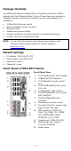
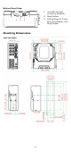
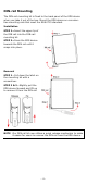
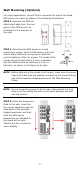
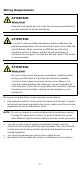
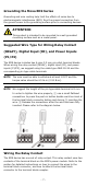
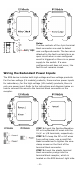
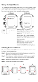
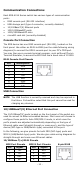
Table Of Contents
- EDS-4014 Series Quick Installation Guide
- Package Checklist
- Default Settings
- Panel Views of EDS-4014 Series
- Mounting Dimensions
- DIN-rail Mounting
- Wall Mounting (Optional)
- Wiring Requirements
- Grounding the Moxa EDS Series
- Suggested Wire Type for Wiring Relay Contact (RELAY), Digital Input (DI), and Power Inputs (P1/P2)
- Wiring the Relay Contact
- Wiring the Redundant Power Inputs
- Wiring the Digital Inputs
- Rotating the Power Module
- Communication Connections
- Reset Button
- Turbo Ring DIP Switch Settings
- LED Indicators
- Specifications

- 9 -
Wiring the Digital Inputs
The EDS device has one set of digital input (DI). The DI consists of two
contacts of the 4-pin terminal block connector on the EDS's right-side
panel. Refer to the instructions and diagram below on how to connect
the wires to the terminal block connector on the receptor.
STEP 1:
Insert the negative
(ground)/positive DI wires into the
┴
/I terminals, respectively.
STEP 2:
To keep the DI wires from
pulling loose, use a
small flat-blade
screwdriver to tighten the wire
-clamp
button
on the front of the terminal
block connector.
STEP 3:
Insert the plastic terminal
block connector prongs into the
terminal block receptor, which is
located on the EDS devices’ right side.
Rotating the Power Module
The power module for the EDS device can be rotated to make it easier
to fit your field site application.
Step 1:
Remove the two screws that fasten the power module to the
EDS device
and remove the module.
Step 2:
Turn the power
module clockwise so that the power, digital
input
, and relay output connectors can be moved upwards.
Step 3:
Replace the module back
on to the EDS device.
Step 4:
Fasten two screws on to the module.