
Installation Guide
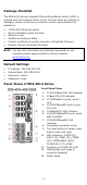
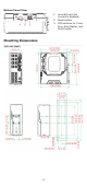
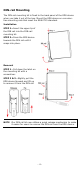
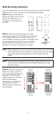
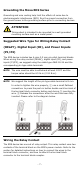
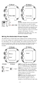
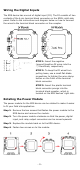
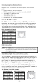
Table Of Contents
- EDS-4014 Series Quick Installation Guide
- Package Checklist
- Default Settings
- Panel Views of EDS-4014 Series
- Mounting Dimensions
- DIN-rail Mounting
- Wall Mounting (Optional)
- Wiring Requirements
- Grounding the Moxa EDS Series
- Suggested Wire Type for Wiring Relay Contact (RELAY), Digital Input (DI), and Power Inputs (P1/P2)
- Wiring the Relay Contact
- Wiring the Redundant Power Inputs
- Wiring the Digital Inputs
- Rotating the Power Module
- Communication Connections
- Reset Button
- Turbo Ring DIP Switch Settings
- LED Indicators
- Specifications

- 4 -
DIN-rail Mounting
The DIN-rail mounting kit is fixed to the back panel of the EDS device
when you take it out of the box. Mount the EDS device on corrosion-
free mounting rails that meet the EN 60715 standard.
Installation
STEP 1—Insert the upper lip of
the DIN r
ail into the DIN-rail
mounting kit.
STEP 2
—Press the EDS device
towards the
DIN rail until it
snaps into place.
Removal
STEP 1
—
Pull down the latch on
the mounting kit with a
screwdriver.
STEP 2
& 3—Slightly pull the
EDS device forward and lift up
to remove it from the DIN rail.
NOTE
Our DIN rail
kit
now utilizes a quick release mechanism to make
it easier for users to remove the DIN rail from the EDS device.