
Installation Guide
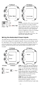
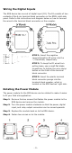
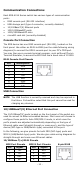
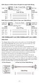
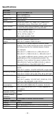
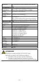
Table Of Contents
- EDS-4014 Series Quick Installation Guide
- Package Checklist
- Default Settings
- Panel Views of EDS-4014 Series
- Mounting Dimensions
- DIN-rail Mounting
- Wall Mounting (Optional)
- Wiring Requirements
- Grounding the Moxa EDS Series
- Suggested Wire Type for Wiring Relay Contact (RELAY), Digital Input (DI), and Power Inputs (P1/P2)
- Wiring the Relay Contact
- Wiring the Redundant Power Inputs
- Wiring the Digital Inputs
- Rotating the Power Module
- Communication Connections
- Reset Button
- Turbo Ring DIP Switch Settings
- LED Indicators
- Specifications

- 11 -
RJ45 (8-pin) to RJ45 (8-pin) Straight-through Cable Wiring
RJ45 (8-pin) to RJ45 (8-pin) Cross-over Cable Wiring
100/1000BaseSFP and 1000/2500BaseSFP (mini-GBIC)
Fiber Port
The Gigabit Ethernet fiber ports on the switch are 100/1000BaseSFP
and 1000/2500BaseSFP fiber ports, which must use 100M,1G, 2.5G
mini-GBIC fiber transceivers to work properly.
The concept behind the LC port and cable is quite straightforward.
Suppose that you are connecting devices I and II; contrary to electrical
signals, optical signals do not require a circuit in order to transmit data.
Consequently, one of the optical lines is used to transmit data from
device I to device II, and the other optical line is used transmit data
from device II to device I, for full-duplex transmission.
Remember to connect the Tx (transmit) port of device I to the Rx
(receive) port of device II, and the Rx (receive) port of device I to the
Tx (transmit) port of device II. If you make your own cable, we suggest
labeling the two sides of the same line with the same letter (A-to-A and
B-to-B, as shown below, or A1-to-A2 and B1-to-B2).
LC-Port Pinouts
LC-Port to LC-Port Cable Wiring