
Installation Guide
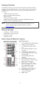
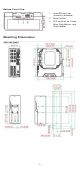
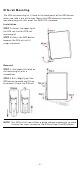
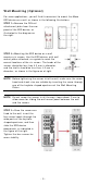
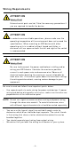
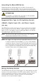

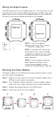
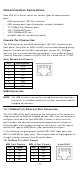
Table Of Contents
- EDS-4014 Series Quick Installation Guide
- Package Checklist
- Default Settings
- Panel Views of EDS-4014 Series
- Mounting Dimensions
- DIN-rail Mounting
- Wall Mounting (Optional)
- Wiring Requirements
- Grounding the Moxa EDS Series
- Suggested Wire Type for Wiring Relay Contact (RELAY), Digital Input (DI), and Power Inputs (P1/P2)
- Wiring the Relay Contact
- Wiring the Redundant Power Inputs
- Wiring the Digital Inputs
- Rotating the Power Module
- Communication Connections
- Reset Button
- Turbo Ring DIP Switch Settings
- LED Indicators
- Specifications

- 8 -
Re la y:
The t wo cont act s of
the 4 -pin t erm inal
block connector are used to det ect
user
-configured event s. The t wo w ires
at tached t o the
fault cont act s for m an
open cir cu i
t w hen a user -configured
event is triggered or
there is no pow er
supply t o t he sw it ch
. I f a u ser-
configured event does not occur, t he
fault cir cu it rem ains closed.
W irin g t he Re dunda n t Pow e r I n put s
The EDS device includes both high - volt age and low - volt age pr oduct s.
For t he low- volt age ( LV m odels) product s, t here are t wo power input s
for r edundancy ; for t he high-volt age ( HV m odels) pr oduct s, t here is
only one pow er input . Refer t o t he inst ruct ion s and diagram below on
how to connect t he wires t o t he term inal block connect or on t he
recept or.
STEP 1 : I nser t t he Posit ive/ Negat ive
DC or Line/ Neutr al AC w ires into t he
V+ / V
- or L/ N t er m inals, respect ively.
STEP 2 :
To keep t he DC or AC wires
fr om pulling loose, use a sm all
flat -
blade scr ew dr iver t o t ight en t he wire
-
clam p screw s on t he front of t he
t erm inal block connect or.
STEP 3 :
I nser t t he plast ic ter m inal
block connect or pron gs int o t he
ter m inal block recept or, w hich is
locat ed on t he EDS devices’ right side.