
Installation Guide

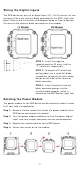
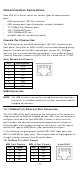
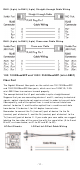
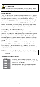
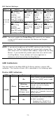
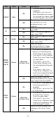
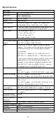
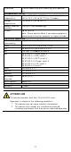
Table Of Contents
- EDS-4014 Series Quick Installation Guide
- Package Checklist
- Default Settings
- Panel Views of EDS-4014 Series
- Mounting Dimensions
- DIN-rail Mounting
- Wall Mounting (Optional)
- Wiring Requirements
- Grounding the Moxa EDS Series
- Suggested Wire Type for Wiring Relay Contact (RELAY), Digital Input (DI), and Power Inputs (P1/P2)
- Wiring the Relay Contact
- Wiring the Redundant Power Inputs
- Wiring the Digital Inputs
- Rotating the Power Module
- Communication Connections
- Reset Button
- Turbo Ring DIP Switch Settings
- LED Indicators
- Specifications

- 14 -
LED
Color
St a t e
De scr ip tion
FAULT Re d
On
1. The r elay cont act has been
t riggered
2. The ingress rat e lim it has
been exceeded and the port
has ent ered shut dow n m ode
3. I nvalid Rin g por t connect ion
Of f
When t he syst em boot s up and
runs corr ect ly or a user -
configured event is not
t riggered.
P1 Am b er
On
Power is being supplied t o power
input PWR.
Of f
Power is not being su pplied t o
power input PWR.
P2 Am b er
On
Power is being supplied t o power
input PWR.
Of f
Power is not being su pplied t o
power input PWR.
M STR/
HEAD
( M/ H)
Gr ee n
On
When t he sw it ch is
Mast er / Head/ Root of Turbo
Ring/ Turbo Chain/ Fast RSTP.
Blin k ing
( 4 t im e s/ se c)
1. The switch has becom e t he
Mast er of Turbo Ring after
Turbo Ring has gone dow n
2. The sw it ch is set as Head of
Turbo Chain and Turbo Chain
has gone down
3. The switch is set as the
Turbo Ring’s Mem ber and
t he corresponding Ring por t
is dow n
4. The switch is set as the
Turbo Chain’s Member/ Tail
and the corr espon ding Head-
end Chain port is down.
Of f
When t he sw itch is not t he
Mast er / Head/ Root of t his Turbo
Rin g/ Turbo Chain/ Fast RSTP.
CPLR/
TAI L
Gr ee n
On
1. The switch’s ring coupling or
dual hom ing function is
enabled.
2. The switch is set as the Tail
of Tur bo Chain.
Blin k ing
( 4 t im e s/ se c)
1. The switch is set as the Tail
of Tur bo Chain and the
Chain has gone down.
2. The switch is set as the
Turbo Chain’s Member/
Head
and t he cor responding Tail-
end Chain port is dow n.
Of f
When the swit ch disables t he
coupling or t ail role of Turbo
Chain.