
Installation Guide

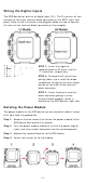
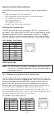
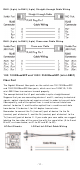
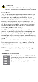
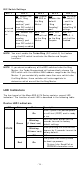
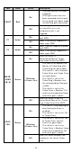
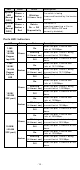
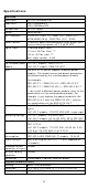
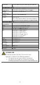
Table Of Contents
- EDS-4014 Series Quick Installation Guide
- Package Checklist
- Default Settings
- Panel Views of EDS-4014 Series
- Mounting Dimensions
- DIN-rail Mounting
- Wall Mounting (Optional)
- Wiring Requirements
- Grounding the Moxa EDS Series
- Suggested Wire Type for Wiring Relay Contact (RELAY), Digital Input (DI), and Power Inputs (P1/P2)
- Wiring the Relay Contact
- Wiring the Redundant Power Inputs
- Wiring the Digital Inputs
- Rotating the Power Module
- Communication Connections
- Reset Button
- Turbo Ring DIP Switch Settings
- LED Indicators
- Specifications

- 11 -
RJ4 5 ( 8 - pin) t o RJ4 5 ( 8 - pin) St ra ig ht - t h rough Ca ble W iring
RJ4 5 ( 8 - pin) t o RJ4 5 ( 8 - pin) Cross- ov er Ca ble W ir ing
1 0 0 / 1 0 0 0 Ba seSFP a nd 1 0 0 0 / 2 5 0 0 BaseSFP ( m ini- GBI C)
Fibe r Port
The Gigabit Ether net fiber por ts on t he switch ar e 100/ 1000BaseSFP
and 1000 / 2500BaseSFP fiber por t s, which m u st use 100M,1G, 2.5G
m in i- GBI C fiber t ransceiver s t o w ork pr operly.
The concept behind the LC port and cable is quit e st raightforw ard.
Suppose t hat you ar e connect ing devices I and I I ; contr ary t o elect r ical
signals, opt ical signals do not require a circuit in or der to t ransm it dat a.
Consequently, one of t he opt ical lines is u sed t o t ransm it dat a from
device I t o device I I , and t he ot her opt ical line is used t ransm it dat a
from device I I t o device I , for full- duplex t r ansm ission.
Rem em ber t o connect t he Tx ( t ransm it ) port of device I to t he Rx
(receive) port of device I I , and the Rx ( receive) port of device I to the
Tx ( t ransm it ) por t of device I I . I f you m ake y our ow n cable, we su ggest
labeling the t wo sides of t he sam e line with t he sam e let t er (A- to- A and
B- t o-B, as shown below , or A1- to- A2 and B1- t o- B2) .
LC- Port Pinout s
LC- Port to LC- Por t Ca ble W irin g