
Installation Guide
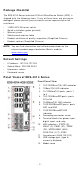
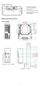
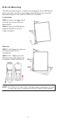
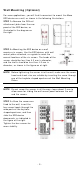
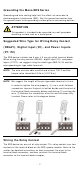

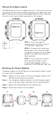
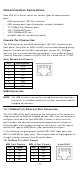
Table Of Contents
- EDS-4014 Series Quick Installation Guide
- Package Checklist
- Default Settings
- Panel Views of EDS-4014 Series
- Mounting Dimensions
- DIN-rail Mounting
- Wall Mounting (Optional)
- Wiring Requirements
- Grounding the Moxa EDS Series
- Suggested Wire Type for Wiring Relay Contact (RELAY), Digital Input (DI), and Power Inputs (P1/P2)
- Wiring the Relay Contact
- Wiring the Redundant Power Inputs
- Wiring the Digital Inputs
- Rotating the Power Module
- Communication Connections
- Reset Button
- Turbo Ring DIP Switch Settings
- LED Indicators
- Specifications

- 10 -
Com m unica t ion Conne ct ions
Each EDS- 4014 Series sw it ch has v arious t ypes of com m unicat ion
port s:
• RJ45 console port ( RS- 232 int erface)
• USB st orage port (t ype A connect or, current ly disabled)
• 10/ 100BaseT( X) Ethernet port s
• 100/ 1000BaseSFP por ts
• 1000/ 2500BaseSFP slot s
• m icroSD car d slot ( curr ent ly disabled)
Con sole Port Con n e ct ion
The EDS dev ice has one RJ45 console por t ( RS-23 2), locat ed on t he
front panel. Use eit her an RJ45- t o- DB9 ( see t he cable follow ing wiring
diagr am s) t o connect t he EDS’s console por t t o your PC’s COM port .
You m ay t hen use a console ter m inal program , such as Moxa PCom m
Ter m inal Em ulat or , t o access t he EDS that has a baud rat e of 1152 00.
RJ4 5 Console Por t Pinou ts
Pin
De scr ip tion
1
DSR
2
RTS
3
–
4
TxD
5
RxD
6
GND
7
CTS
8
DTR
USB Conn e ct ion
N OTE
The USB funct ion is current ly reser ved and m ay be required in
the fut ure. I t should be not ed t hat this port cannot be used for
char ging any devices.
1 0 / 1 0 0 Ba seT( X) Et her net Port Conne ct ion
The 10/ 100BaseT( X) por t s locat ed on the front panel of the switch ar e
used t o connect t o Ether net-enabled devices. Most user s w ill choose t o
configure t hese port s for Aut o MDI / MDI - X m ode, in w hich case t he
por t’s pinout s are adj ust ed aut om at ically depending on t he t ype of
Ethernet cable used ( st raight - thr ough or cr oss- over ), and t he t ype of
device ( NI C-t ype or HUB/ Sw it ch - t ype) connected to the port .
I n t he follow ing, we give pinout s for bot h MDI ( NI C- t ype) por t s an d
MDI - X ( HUB/ Sw it ch-t ype) port s. We also give cable wiring diagram s for
st raight - through and cr oss- over Et her net cables.
1 0 / 1 0 0 Ba se T( x ) RJ4 5 Pinout s
MD I Port Pinout s
MDI - X Por t Pinou ts
8 - pin RJ4 5
Pin
Sign al
1
Tx+
2
Tx-
3
Rx+
6
Rx-
Pin
Sign al
1
Rx+
2
Rx-
3
Tx+
6
Tx-