EDS-305 Quick Installation Guide Moxa EtherDevice Switch Edition 10.0, February 2017 Technical Support Contact Information www.moxa.
Overview Moxa’s EtherDevice™ EDS-305 are smart Ethernet switches that provide an economical solution for your Ethernet connections. As an added bonus, the built-in smart alarm function helps system maintainers monitor the health of your Ethernet network. The EDS-305 have a wide operating temperature range of -40 to 75°C, and are designed to withstand a high degree of vibration and shock.
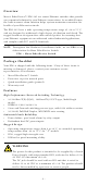
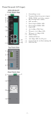
Panel Layout 1. 2. 3. 4. 5. 6. 7. 8. 9. 10. 11. 12. 13.
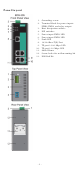
Panel Layout (SC-type) NOTE: The appearance of EDS-305-S-SC is identical to EDS-305-M-SC 1. 2. 3. 4. 5. 6. 7. 8. 9. 10. 11. 12. 13. 14. 15.
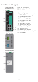
Panel Layout (ST-type) 1. 2. 3. 4. 5. 6. 7. 8. 9. 10. 11. 12. 13. 14. 15.
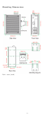
Mounting Dimensions Unit = mm (inch) -6-
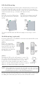
DIN-Rail Mounting The aluminum DIN-rail attachment plate should already be fixed to the back panel of the EDS when you take it out of the box. If you need to reattach the DIN-rail attachment plate, make sure the stiff metal spring is situated towards the top, as shown in the figures below. STEP 1: Insert the top of the DIN-rail into the slot just below the stiff metal spring. STEP 2: The DIN-rail attachment unit will snap into place as shown below.
STEP 3: Once the screws are fixed in the wall, insert the four screw heads through the large parts of the keyhole-shaped apertures, and then slide the EDS downwards, as indicated. Tighten the four screws for added stability. ATEX Information 1. 2. 3. 4. 5.
WARNING This unit is a built-in type. When the unit is installed in another piece of equipment, the equipment enclosing the unit must comply with fire enclosure regulation IEC 60950/EN60950 (or similar regulation). WARNING Safety First! Be sure to disconnect the power cord before installing and/or wiring your Moxa EtherDevice Switch. Calculate the maximum possible current in each power wire and common wire. Observe all electrical codes dictating the maximum current allowable for each wire size.
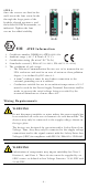
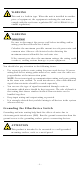
Wiring the Alarm Contact The Alarm Contact consists of the two middle contacts of the terminal block on EDS’s top panel. You may refer to the next section for detailed instructions on how to connect the wires to the terminal block connector, and how to attach the terminal block connector to the terminal block receptor. In this section, we explain the meaning of the two contacts used to connect the Alarm Contact.
Communication Connections EDS-305 models have 4 or 5 10/100BaseT(X) Ethernet ports, and 1 or 0 (zero) 100 BaseFX (SC/ST-type connector) fiber ports. 10/100BaseT(X) Ethernet Port Connection The 10/100BaseT(X) ports located on the EDS’s front panel are used to connect to Ethernet-enabled devices. Below we show pinouts for both MDI (NIC-type) ports and MDI-X (HUB/Switch-type) ports, and also show cable wiring diagrams for straight-through and cross-over Ethernet cables.
100BaseFX Ethernet Port Connection The concept behind the SC/ST port and cable is quite straightforward. Suppose you are connecting devices I and II. Contrary to electrical signals, optical signals do not require a circuit in order to transmit data. Consequently, one of the optical lines is used to transmit data from device I to device II, and the other optical line is used transmit data from device II to device I, for full-duplex transmission.
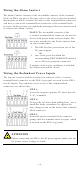
The Alarm Contact has two terminals that form a Fault circuit for connecting to an alarm system. The two wires attached to the Fault contacts form an open circuit when (1) EDS has lost power from one of the DC power inputs, or (2) one of the ports for which the corresponding PORT ALARM DIP Switch is set to ON is not properly connected. If neither of these two conditions occurs, the Fault circuit will be closed. DIP Switch Settings EDS-305 Series DIP Switches ON: Enables the corresponding PORT Alarm.
Fiber Ports The EDS’s fiber switched ports operate at a fixed 100 Mbps speed and full-duplex mode to provide the best performance. The fiber ports are factory-built as either a multi-mode or single-mode SC/ST connector. Consequently, you should use fiber cables that have SC/ST connectors at both ends. When plugging the connector into the port, make sure the slider guide is positioned to the right side so that it fits snuggly into the port.
Switching and Address Learning The EDS has an address table that can hold up to 1K node addresses, which makes it suitable for use with large networks. The address tables are self-learning, so that as nodes are added or removed, or moved from one segment to another, the EDS automatically keeps up with new node locations. An address-aging algorithm causes the least-used addresses to be deleted in favor of newer, more frequently used addresses.
Optical Fiber 5 1300 -20 -14 -34 to -30 Single mode, 15 15 1310 -15 -6 -36 to -32 Single mode, 40 40 1310 -5 0 -36 to -32 Single mode, 80 80 1550 -5 0 -36 to -32 50/125 9/125 9/125 9/125 Multi-mode Distance, km Wavelength, nm Min. TX Output, dBm Max. TX Output, dBm Sensitivity, dBm Recommended Diameter (Core/Cladding) μm (1 dB/km, 800 MHz x km) Power Input Voltage Input Current 12 to 48 VDC, redundant inputs EDS-305: 0.13 A @ 24 V EDS-305-M/S: 0.17 A @ 24 V Removable “6-pin” Terminal Block 1.