EDS-2016-ML Series Quick Installation Guide Moxa EtherDevice Switch Version 1.0, November 2019 Technical Support Contact Information www.moxa.
Overview The EDS-2016-ML Series industrial Ethernet switches have 16 10/100M ports and up to two optical fiber ports with SC/ST connector type options. The EDS-2016-ML provides 12/24/48 VDC redundant power inputs, and the switches are available with a standard operating temperature range from -10 to 60°C, or with a wide operating temperature range from -40 to 75°C. The switches are rugged enough to operate reliably in harsh industrial environments.
Features High Performance Network Switching Technology • • • • 10/100BaseT(X) auto-negotiation speed, full/half duplex mode, auto MDI/MDI-X connection, and 100BaseFX (SC/ST type, Multi/Single mode). IEEE 802.3 for 10BaseT, IEEE 802.3u for 100BaseT(X) and 100BaseFX. IEEE 802.1p for Quality of Service (QoS) traffic prioritized function. Store-and-forward switching process type.
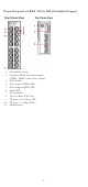
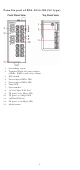
Panel Layout of EDS-2016-ML (Standard type) 1. 2. 3. 4. 5. 6. 7. 8. 9. 10. 11.
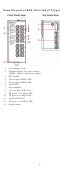
Panel Layout of EDS-2016-ML (SC type) 1. 2. 3. 4. 5. 6. 7. 8. 9. 10. 11. 12. 13.
Panel Layout of EDS-2016-ML (ST type) 1. 2. 3. 4. 5. 6. 7. 8. 9. 10. 11. 12. 13.
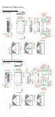
Mounting Dimensions EDS-2016-ML Series EDS-2016-ML Fiber Series -7-
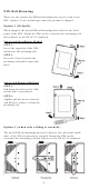
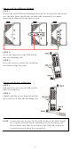
DIN-Rail Mounting There are two options for DIN-rail mounting that can be used on an EDS. Option 1 is the default type when the product is shipped. Option 1 (Default): When shipped, the metal DIN-rail mounting kit is fixed to the back panel of the EDS. Mount the EDS on the corrosion-free mounting rail that adheres to the EN 60715 standard. Suggested Installation Method STEP 1: Insert the upper lip of the DINrail kit into the mounting rail.
Suggested Installation Method STEP 1: Detach the metal DIN-rail mounting kit from the back panel and attach it to the side panel (mold side) in either the horizontal or vertical direction as indicated in the figure below. STEP 2: Insert the upper lip of the DIN-rail kit into the mounting rail. STEP 3: Press the device towards the mounting rail until it snaps into place. Suggested Removal Method STEP 1: Pull down the latch on the DIN-rail kit with a screwdriver.
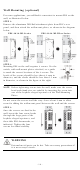
Wall Mounting (optional) For some applications, you will find it convenient to mount EDS on the wall, as illustrated below. STEP 1: Remove the aluminum DIN-Rail attachment plate from EDS’s rear panel, and then attach the wall mount plates, as shown in the diagram below. EDS-2016-ML Series EDS-2016-ML Fiber Series STEP 2: Mounting EDS on the wall requires 4 screws. Use the switch, with wall mount plates attached, as a guide to mark the correct locations of the 4 screws.
Wiring Requirements WARNING Do not disconnect modules or wires unless the power supply has been switched off or the area is known to be nonhazardous. The devices may only be connected to the supply voltage shown on the type plate. The devices are designed for operation with a Safety Extra-Low Voltage. Thus, they may only be connected to the supply voltage connections and to the signal contact with the Safety Extra-Low Voltages (SELV) in compliance with IEC950/ EN60950/ VDE0805.
ATTENTION This product is intended to be mounted to a well-grounded mounting surface, such as a metal panel. Wiring the Alarm Contact The Alarm Contact consists of the two middle contacts of the terminal block on EDS’s top panel. You may refer to the next section for detailed instructions on how to connect the wires to the terminal block connector, and how to attach the terminal block connector to the terminal block receptor.
ATTENTION One individual conductor in a clamping point with 28-14 AWG wire size, and a torque value of 1.7 lb-in should be used. Communication Connections The EDS-2016-ML models have 14 or 16 10/100BaseT(X) Ethernet ports, and 0 or 2 100BaseFX (SC/ST-type connector) fiber ports. 10/100BaseT(X) Ethernet Port Connection The 10/100BaseT(X) ports located on the EDS’s front panel are used to connect to Ethernet-enabled devices.
signals, optical signals do not require a circuit in order to transmit data. Consequently, one of the optical lines is used to transmit data from device I to device II, and the other optical line is used transmit data from device II to device I, for full-duplex transmission. All you need to remember is to connect the Tx (transmit) port of device I to the Rx (receive) port of device II, and the Rx (receive) port of device I to the Tx (transmit) port of device II.
corresponding PORT ALARM DIP Switch is set to ON is not properly connected. If neither of these two conditions occurs, the Fault circuit will be closed. NOTE The DIP settings will be activated when the device is powered on the next time. DIP Switch Settings EDS-2016-ML Series DIP Switches DIP Switch Port Alarm Function P1 to P16 Setting ON OFF Quality of Service (QoS) ON Description Enables the corresponding PORT Alarm.
LED Color 100M Fiber Green LED 10M/100M Copper top Green LED 10M/100M Copper Green bottom LED State Description When the corresponding PORT alarm is enabled and the port’s link is active, or Off when the corresponding PORT alarm is disabled. On TP port’s 100Mbps link is active. Blinking Data is being transmitted at 100Mbps. Off TP port’s 100Mbps link is inactive. On TP port’s 100Mbps link is active. Blinking Data is being transmitted at 100Mbps. Off TP port’s 100Mbps link is inactive.
Switching, Filtering, and Forwarding Each time a packet arrives at one of the switched ports, a decision is made to either filter or forward the packet. Packets with source and destination addresses belonging to the same port segment will be filtered, constraining those packets to one port, and relieving the rest of the network from the need to process them.
Specifications Technology Standards Flow Control Interface RJ45 Ports Fiber Ports LED Indicators DIP Switch Alarm Contact IEEE 802.3 for 10BaseT, IEEE 802.3u for 100BaseT(X) and 100Base FX, IEEE 802.1p for Class of Service EEE 802.
Input Current Connection Overload Current Protection Reverse Polarity Protection Mechanical Casing Dimensions (W x H x D) EDS-2016-ML: 0.296 A (max.) EDS-2016-ML-MM-SC: 0.443 A (max.) EDS-2016-ML-MM-ST: 0.458 A (max.) EDS-2016-ML-SS-SC: 0.460 A (max.) Relay output: 24 VDC, 1 A, Resistance Removable 6-contact terminal block 28-14 AWG, 1.7 lb-in All wires must be able to withstand at least 85°C Present Present IP30 protection, metal case EDS-2016-ML Copper model: 36 x 135 x 95 mm (1.41 x 5.31 x 3.