EDS-2010/2018-ML Series Quick Installation Guide Moxa EtherDevice Switch Version 1.1, August 2019 Technical Support Contact Information www.moxa.
Overview The EDS-2010/2018-ML series of industrial Ethernet switches are equipped with 8/16-ports 10/100M copper ports and 2 10/100/1000BaseT(X) or 100/1000BaseSFP combo ports. The switches are ideal for applications that require high-bandwidth data convergence and long-distance uplinks. The EDS-2010/2018-ML provides 12/24/48 VDC redundant power inputs, and the switches are available with a standard operating temperature range from -10 to 60°C, or with a wide operating temperature range from -40 to 75°C.
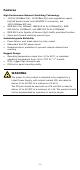
Features High Performance Network Switching Technology • • • • 10/100/1000BaseT(X), 10/100BaseT(X) auto-negotiation speed, full/half duplex mode, auto MDI/MDI-X connection, and 100/1000Base SFP slot. IEEE 802.3 for 10BaseT, IEEE 802.3u for 100BaseT(X), IEEE 802.3ab for 1000BaseT, and IEEE 802.3z for 1000BaseX. IEEE 802.1p for Quality of Service (QoS) traffic prioritized function. Store-and-forward switching process type.
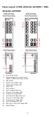
Panel Layout of EDS-2010-ML-2GTXSFP / EDS2018-ML-2GTXSFP 1. 2. 3. 4. 5. 6. 7. 8. 9. 10. 11. 12. 13. 14. 15. 16.
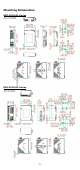
Mounting Dimensions EDS-2010-ML Series EDS-2018-ML Series -5-
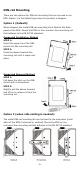
DIN-rail Mounting There are two options for DIN-rail mounting that can be used on an EDS. Option 1 is the default type when the product is shipped. Option 1 (Default): When shipped, the metal DIN-rail mounting kit is fixed to the back panel of the EDS. Mount the EDS on the corrosion-free mounting rail that adheres to the EN 60715 standard. Suggested Installation Method STEP 1: Insert the upper lip of the DINrail kit into the mounting rail.
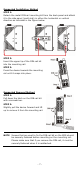
Suggested Installation Method STEP 1: Detach the metal DIN-rail mounting kit from the back panel and attach it to the side panel (mold side) in either the horizontal or vertical direction as indicated in the figure below. STEP 2: Insert the upper lip of the DIN-rail kit into the mounting rail. STEP 3: Press the device towards the mounting rail until it snaps into place. Suggested Removal Method STEP 1: Pull down the latch on the DIN-rail kit with a screwdriver.
Wall Mounting (optional) For some applications, you will find it convenient to mount EDS on the wall, as illustrated below. STEP 1: Remove the aluminum DIN-Rail attachment plate from EDS’s rear panel, and then attach the wall mount plates, as shown in the diagram below. EDS-2010-ML Series EDS-2018-ML Series STEP 2: Mounting EDS on the wall requires 4 screws. Use the switch, with wall mount plates attached, as a guide to mark the correct locations of the 4 screws.
Wiring Requirements WARNING Do not disconnect modules or wires unless the power supply has been switched off or the area is known to be nonhazardous. The devices may only be connected to the supply voltage shown on the type plate. The devices are designed for operation with a Safety Extra-Low Voltage. Thus, they may only be connected to the supply voltage connections and to the signal contact with the Safety Extra-Low Voltages (SELV) in compliance with IEC950/ EN60950/ VDE0805.
Grounding Moxa EtherDevice Switch Grounding and wire routing help limit the effects of noise due to electromagnetic interference (EMI). Run the ground connection from the ground screw to the grounding surface prior to connecting devices. A 4 mm2 conductor must be used when a connection to the external grounding screw is utilized. ATTENTION This product is intended to be mounted to a well-grounded mounting surface, such as a metal panel.
Wiring the Redundant Power Inputs The top two contacts and the bottom two contacts of the 6-contact terminal block connector on the EDS’s top panel are used for the EDS’s two DC inputs. Top and front views of one of the terminal block connectors are shown here. STEP 1: Insert the negative/positive DC wires into the V-/V+ terminals. STEP 2: To keep the DC wires from pulling loose, use a small flat-blade screwdriver to tighten the wire-clamp screws on the front of the terminal block connector.
10/100Base T(x) RJ45 Pinouts MDI Port Pinouts Pin 1 2 3 6 Signal Tx+ TxRx+ Rx- MDI-X Port Pinouts Pin 1 2 3 6 8-pin RJ45 Signal Rx+ RxTx+ Tx- RJ45 (8-pin) to RJ45 (8-pin) Straight-through Cable Wiring RJ45 (8-pin) to RJ45 (8-pin) Cross-over Cable Wiring 10/100/1000BaseT(X) Ethernet Port Connection The 10/100/1000BaseT(X) ports located on Moxa EtherDevice Switch’s front panel are used to connect to Ethernet-enabled devices.
1000BaseT RJ45 Pinouts Pin 1 2 3 4 5 6 7 8 MDI BI_DA+ BI_DABI_DB+ BI_DC+ BI_DCBI_DBBI_DD+ BI_DD- MDI-X BI_DB+ BI_DBBI_DA+ BI_DD+ BI_DDBI_DABI_DC+ BI_DC- RJ45 (8-pin) to RJ45 (8-pin) Straight-through Cable Wiring RJ45 (8-pin) to RJ45 (8-pin) Cross-over Cable Wiring - 13 -
100/1000Base-X Fiber Port The Fiber ports on the EDS-2010/2018-ML Series are SFP type slots, which support both 100Base-FX and 1000Base-X speeds. Moxa provides complete transceiver models for various distance requirements. The concept behind the LC port and cable is quite straightforward. Suppose you are connecting devices I and II. Unlike electrical signals, optical signals do not require a circuit in order to transmit data.
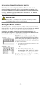
connected. If neither of these two conditions occurs, the Fault circuit will be closed. NOTE The DIP settings will be activated when the device is powered on the next time. DIP Switch Settings EDS-2010-ML Series DIP Switches DIP Switch Port Alarm Function P1 to P8 P9 is G1 P10 is G2 Setting ON OFF Quality of ON Service (QoS) Description Enables the corresponding PORT Alarm. If the port’s link fails, the relay will form an open circuit and the fault LED will light up.
EDS-2018-ML Series DIP Switches DIP Switch Port Alarm Function P1 to P16 P17 is G1 P18 is G2 Setting ON OFF Quality of ON Service (QoS) Description Enables the corresponding PORT Alarm. If the port’s link fails, the relay will form an open circuit and the fault LED will light up. Disables the corresponding PORT Alarm. The relay will form a closed circuit and the Fault LED will never light up. Enable the Quality of Service to handle packet priorities in four WRR queues.
LED Color 10M/100M/ 1000M Copper Bottom LED Green State On Blinking Off On 10M/100M Copper Top LED Green 10M/100M Copper Bottom LED Green Blinking Off On Blinking Off On Green Blinking Off 100M/1000M (SFP port) On Amber Blinking Off Description TP port’s 10/100Mbps link is active. Data is being transmitted at 10/100Mbps. TP port’s 10/100Mbps link is inactive. TP port’s 100Mbps link is active. Data is being transmitted at 100Mbps. TP port’s 100Mbps link is inactive.
Switching, Filtering, and Forwarding Each time a packet arrives at one of the switched ports, a decision is made to either filter or forward the packet. Packets with source and destination addresses belonging to the same port segment will be filtered, constraining those packets to one port, and relieving the rest of the network from the need to process them.
Specifications Technology Standards Flow Control Interface RJ45 Ports Fiber Ports LED Indicators DIP Switch Alarm Contact IEEE 802.3 for 10BaseT, IEEE 802.3u for 100BaseT(X) and 100Base FX, IEEE 802.3ab for 1000BaseT, IEEE 802.3z for 1000BaseSX/LX/LHX/ZX IEEE 802.1p for Class of Service IEEE 802.
Regulatory Approvals Safety UL 61010-2-201, EN 62368-1(LVD) EMI FCC Part 15, CISPR (EN55032) class A EMS EN61000-4-2 (ESD), Level 3 EN61000-4-3 (RS), Level 3 EN61000-4-4 (EFT), Level 3 EN61000-4-5 (Surge), Level 3 EN61000-4-6 (CS), Level 3 EN61000-4-8 Hazardous UL/cUL Class I, Division 2, Groups A, B, C, and D; Location* ATEX Zone 2, Ex nA nC IIC T4 Gc Maritime* DNV GL, ABS, LR, NK Rail Traffic* EN 50121-4 Traffic Control NEMA TS2 Shock IEC60068-2-27 Free Fall IEC60068-2-32 Vibration IEC60068-2-6 WARRANTY 5