
Installation Guide
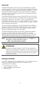
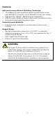
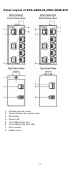

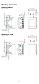
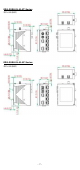
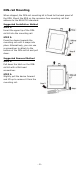
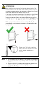
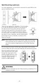
Table Of Contents
- EDS-2008-EL/ELP Series Quick Installation Guide
- Overview
- Package Checklist
- Features
- Panel Layout of EDS-2008-EL/EDS-2008-ELP
- Panel Layout of EDS-2008-EL-M-ST/EDS-2008-EL-M-SC
- Mounting Dimensions
- DIN-rail Mounting
- Wall Mounting (optional)
- Wiring Requirements
- Grounding the Moxa EtherDevice Switch
- Wiring the Power Input
- Communication Connections
- 100BaseFX Ethernet Port Connection
- DIP Switch Settings
- LED Indicators
- Auto MDI/MDI-X Connection
- Dual Speed Functionality and Switching
- Switching, Filtering, and Forwarding
- Switching and Address Learning
- Auto-negotiation and Speed Sensing
- Specifications

- 9 -
ATTENTION
When installing or removing the devices, please insert a flat
-
head screwdriver into the latch of the holding clamp and pull
the
latch downward rather than pushing it towards the DIN rail
side,
when removing the module from the rail.
If you want to change the position of the device on the DIN rail,
please follow the steps shown in the image
s above. First,
remove the device using a flat
-head screwdriver and then re-
install the device in the desired position. Please DO NOT directly
move the device on the DIN rail, without uninstalling it first.
If the equipment is used in a manner not specified
by the
manufacturer, the protection provided by the equipment may
be impaired.
Please use a flat
-head screwdriver
with a head size of between 4 and 6
mm for proper installation or
removal.
NOTE
1.
The installation and the safety of any system incorporating
the equipment is the responsibility of the assembler of the
system.
2.
This is an OPEN TYPE module and should be installed in a
safety enclosure with mechanical rigidity and an
appropriate IP rating.