
Installation Guide
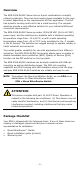
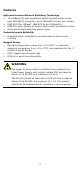
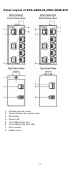

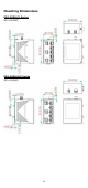
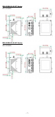
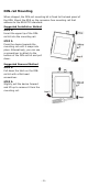
Table Of Contents
- EDS-2008-EL/ELP Series Quick Installation Guide
- Overview
- Package Checklist
- Features
- Panel Layout of EDS-2008-EL/EDS-2008-ELP
- Panel Layout of EDS-2008-EL-M-ST/EDS-2008-EL-M-SC
- Mounting Dimensions
- DIN-rail Mounting
- Wall Mounting (optional)
- Wiring Requirements
- Grounding the Moxa EtherDevice Switch
- Wiring the Power Input
- Communication Connections
- 100BaseFX Ethernet Port Connection
- DIP Switch Settings
- LED Indicators
- Auto MDI/MDI-X Connection
- Dual Speed Functionality and Switching
- Switching, Filtering, and Forwarding
- Switching and Address Learning
- Auto-negotiation and Speed Sensing
- Specifications

- 8 -
DIN-rail Mounting
When shipped, the DIN-rail mounting kit is fixed to the back panel of
the EDS. Mount the EDS on the corrosion-free mounting rail that
adheres to the EN 60715 standard.
Suggested Installation Method
STEP 1:
Insert the upper lip of the DIN
-
rail kit into the mounting rail.
S
TEP 2:
Press the device towards the
mounting rail until it snaps into
place.
Alternatively, you can use
a screwdriver to attach to the
bottom of the DIN
-
rail kit and pull
down.
Suggested Removal Method
STEP 1:
Pull down the latch on the DIN
-
rail kit wit
h a flat-head
screwdriver.
STEP 2:
Slightly pull the device forward
and lift up to remove it from the
mounting rail.