
Installation Guide


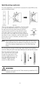


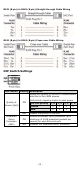

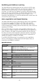

Table Of Contents
- EDS-2005-EL/ELP Series Quick Installation Guide
- Overview
- Package Checklist
- Features
- Panel Layout of EDS-2005-EL/EDS-2005-ELP
- Mounting Dimensions
- DIN-rail Mounting
- Wall Mounting (optional)
- Wiring Requirements
- Grounding the Moxa EtherDevice Switch
- Wiring the Power Input
- Communication Connections
- DIP Switch Settings
- LED Indicators
- Auto MDI/MDI-X Connection
- Dual Speed Functionality and Switching
- Switching, Filtering, and Forwarding
- Switching and Address Learning
- Auto-negotiation and Speed Sensing
- Specifications

- 11 -
NOTE
The power source comes from secondary circuits. These circuits
are separated from mains circuits by a transformer in which the
primary windings are separated from the secondary windings
by reinforced installation, double installation, or a screen
connected to the protective conductor terminal.
ATTENTION
Before connecting
the EDS to the DC power inputs, make sure
the DC power source voltage is stable.
ATTENTION
One individual conductor in a
clamping point with 28-14 AWG
wire size, and a torque value of 1.7 lb-in should be used.
ATTENTION
The
cable that is connected to the field wiring terminals must
be capable of withstanding at least 105°C.
Communication Connections
The EDS-2005-EL/ELP models have 10/100BaseT(X) Ethernet ports.
10/100BaseT(X) Ethernet Port Connection
The 10/100BaseT(X) ports located on the EDS’s front panel are used to
connect to Ethernet-enabled devices.
Below we show pinouts for both MDI (NIC-type) ports and MDI-X
(HUB/Switch-type) ports, and show cable wiring diagrams for straight-
through and cross-over Ethernet cables.
10/100Base T(x) RJ45 Pinouts
MDI Port Pinouts
MDI-X Port Pinouts
8-pin RJ45
Pin
Signal
1
Tx+
2
Tx-
3
Rx+
6
Rx-
Pin
Signal
1
Rx+
2
Rx-
3
Tx+
6
Tx-