
User`s manual


CP-134U Series User’s Manual Connection Cables and Cable Wiring
5-2
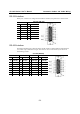
RS-232 Interface
When ports 1 and/or 2 are configured for the RS-232 interface, the pinouts are as shown below.
CP-134U (RS-232)
Port 1 Port 2
13 TxD 9 TxD
14 RxD 10 RxD
15 RTS 11 RTS
28 CTS 24 CTS
29 DTR 25 DTR
30 DSR 26 DSR
42 DCD 39 DCD
44 GND 41 GND
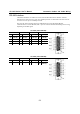
RS-422 Interface
The RS-422 standard uses a balanced voltage digital interface to allow 9600 bps communication
over cables of up to 4000 feet in length. Ten receivers can be connected to any one driver for
broadcasting systems.
CP-134U (RS-422)
Port 1 Port 2 Port 3 Port 4
13 RxD+(B) 9 RxD+(B) 5 RxD+(B)
1RxD+(B)
14 TxD+(B) 10 TxD+(B) 6 TxD+(B)
2TxD+(B)
15 RTS+(B) 11 RTS+(B) 7 RTS+(B) 3 RTS+(B)
28 CTS+(B) 24 CTS+(B) 20 CTS+(B) 16 CTS+(B)
29 RxD-(A) 25 RxD-(A) 21 RxD-(A) 17 RxD-(A)
30 RTS-(A) 26 RTS-(A) 22 RTS-(A) 18 RTS-(A)
42 TxD-(A) 39 TxD-(A) 35 TxD-(A) 31 TxD-(A)
43 CTS-(A) 40 CTS-(A) 36 CTS-(A) 32 CTS-(A)
44 GND 41 GND 37 GND 33 GND