
User`s manual


CP-134U Series User’s Manual Hardwareware Installation
2-3
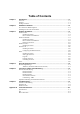
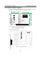
CP-134U V2 (120 x 82.5mm)
120 mm [4.72 in]
82.5mm
[3.2 4 i n]
41.7 mm
[1.64 in]
MU860
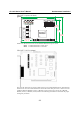
CP-134U V2
121 mm
[4.7 6 i n]
101 mm
[3.9 7 i n]
4 WIRE RS422
Port1
Port2
JP4
JP3
Port3
Port4
JP2
JP1
NOTE: Use JP1/2/3/4 to activate the Termination Resistors for ports 1/2/3/4.
Open Termination Resistor is NOT active
Short Termination Resistor is ACTIVE
CP-134U V1 (135 x110mm)
The CP-134U Series has two 30-pin jumpers and two sets of four DIP Switches on the board that
allow the user to set the serial interface for each of the board’s four ports. Ports 1 and 2 can be set
to RS-232, RS-422, RS-485 (2-wire), or RS-485 (4-wire). Ports 3 and 4 can be set to RS-422,
RS-485 (2-wire), or RS-485 (4-wire). Refer to the following information to determine the proper
settings for your board.