
User`s manual


Table Of Contents
Hardware Installation
Intellio C320Turbo/PCI User's Manual 2-9
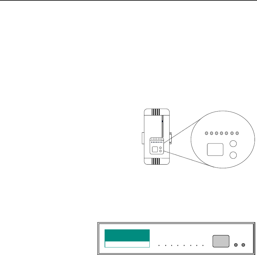
If the first test passed, the CPU/Basic Module will then display “Ld” waiting for
loading firmware from the Intellio C320Turbo/PCI Control Board. After loading
the firmware, the CPU Module will scan for the number of UART Modules or the
number of ports available. The LED will show the last accessible port.
CPU Module
The left digit shows the UART Module number and the right digit shows the last
port number within a UART Module. The UART Module closest to the CPU
Module is of number 1. The next module is of number 2, and so on. For example, if
“48” is displayed, it means that the last accessible port is the eighth port of the fourth
UART Module.
Basic Module
The left digit shows the number of 8-port unit that configured (if continuous 8 ports
are considered as an 8-port unit) and the right digit shows the last port number
within an 8-port unit. For example, if “48” is displayed, it means that the last
accessible port is the eighth port of the fourth 8-port unit.
To see a particular port’s line status, you can keep pressing Module Button and
Channel (Port) Button till the desired port is shown on LED display, then look at the
seven indicators TxD, RxD, DTR, DSR, RTS, CTS, and DCD. This provides a
convenient diagnostic ways for Intellio C320Turbo/PCI. Normally, DTR and RTS
CPU Module
4
8
CHANNEL
MODULE
TRDDRCD
XXTSTTC
DDRRSSD
Multi
p
ort Controlle
r
B
asi
c
﹙
o
﹙
d
﹙
u
﹙
le
P
owe
r
TxD
R
xD
D
TR
D
SR
R
T
S
CTS
D
CD
M
odule Channel
Basic Module
48
M