
User`s manual


Table Of Contents
2-8 Intellio C320Turbo/PCI User's Manual
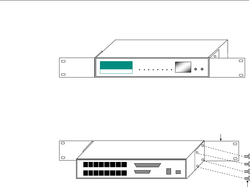
To mount the module(s) on the industrial standard 19” rack, Rack Mount
Kit, including two L-type plates and eight screws, should be applied.
Multi
p
ort Controller with Rack Mount Kit installed
(
Front View
)
L-type Plate
L-type Plate
Multiport Controller
BA
S
I
C
M
O
DULE
P
owe
r
TxD
R
xD
D
TR
D
SR
R
T
S
CT
S
D
CD
M
odule Channe
l
Step 9: After making sure that each component has been correctly installed, you
are recommended to power on the Basic Module first and then power on
the PC system secondly.
☞ Now the installation of the external Basic/Extensive module is complete.
Continue to install the software driver explained in chapter 3.
Operating LED Indicators
After completing the installation and powering on the CPU/Basic Module and the
PC system, check the two-digit LED display on the CPU/Basic Module. These LEDs
show the results of the system self-diagnostic tests, which are run by the CPU/Basic
Module after startup.
The CPU/Basic Module will first test the ROM and RAM of itself, and then
UART/Extensive Module(s) if present. If any error is found, the LED display will
show one of the messages described in “Troubleshooting” chapter.
Multiport Controller with Rack Mount Kit installed ( Rear View )
L-t
yp
e Plate
L-type Plate
Screw