
User`s manual


Table Of Contents
2-4 Intellio C320Turbo/PCI User's Manual
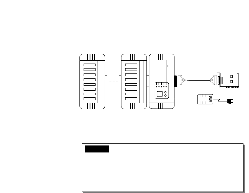
B: Plug the DB25 male end of the shipped 2-meter 10-signal-pin cable
(the link cable comes with long range extension kit or the one
fabricated according to the pinouts in the chapter 5) into the connector
on the rear panel of the Intellio C320Turbo /PCI Control Board.
2
3
4
5
6
7
8
1
2
3
4
5
6
7
8
1
00
Power Adapter
UART Module
UART Module
CPU Module
10-signal-pin
Cable
C320 Tur bo/PCI
C: Plug the other DB25 female end into the CPU Module’s DB25
connector.
Warning! Do not use a 25-signal-pin cable to connect the
Intellio C320Turbo /PCI Control Board to the CPU
Module when using the power adapter as this will
cause power crash. (One power comes from the
power adapter while the other power comes from the
Intellio C320Turbo /PCI Control Board.)
D: Connect the power adapter to the CPU Module. Keep the CPU
Module’s power switch in the OFF position. If UART Module(s) is
(are) also required, keep the CPU Module’s power switch in the OFF
position until all necessary UART Module(s) is (are) installed.
E: Install the power adapter to a power source, either 110V or 220V AC.
Adjustment to the AC power specs is done automatically.