
Installation guide


— 7 —
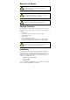
ATTENTION
This product is intended to be supplied by a Listed Power Unit
marked “Class 2” or “LPS” and rated O/P: 12 to 48 VDC,
minimum 6 W (12 V/0.494 A to 48V/0.121 A).
Make sure the External Power Adaptor (including power cords
and plug assemblies) provided with the unit is certified and
suitable for use in your country.
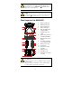
Before connecting the AWK-6222 to the DC power inputs, make
sure the DC power source voltage is stable.
Please also note, the PoE networks can not route to the outside
plant.
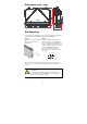
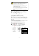
Wiring the Digital Inputs and Relay
Contact (Digital Output)
The AWK-6222 has two sets of digital input—DI1 and DI2. Each DI
comprises two contacts of the 8-pin M12 connector on the AWK-6222’s
bottom panel. These two digital inputs can be connected to
digital-output-enabled sensors for on-site status monitoring.
The AWK-6222 also has one relay output, which consists of the two contacts.
These relay contacts are used to detect user-configured events. The two wires
attached to the relay contacts form an open circuit when a user-configured
event is triggered. If a user-configured event does not occur, the relay circuit
will be closed.
A field-installable plug, M12A-8PMM-IP68, is recommended for connecting
the AWK-6222’s DIs and relay.
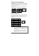
Pin Signal
1
2
Relay
3 DI1 I1
4 DI1 COM_1
5 DI2 I2
6 DI2 COM_2
7
8
Reserved