
Installation guide


— 2 —
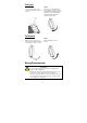
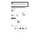
ATTENTION
For security reasons, we strongly recommend changing the
password. To do so, go to Maintenance Æ Password, and then
follow the on-screen instructions.
NOTE
To make the change effective, you must save the change and then
click Restart Æ Save and Restart button to apply all changes.
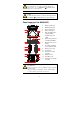
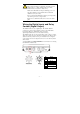
Panel Layout of the AWK-6222
2
3
3
1
8
7
4
5
6
9
9
10
10
4
4
1
2
3
12
14
13
11
Front Panel View
Top Panel View
Bottom Panel View
Side Panel View
Rear Panel View
1. MAIN 1 antenna port.
2. MAIN 2 antenna port.
3. AUX 1 antenna port.
4. AUX 2 antenna port.
5. LEDs for PWR, FAULT,
STATE, WLAN1,
WLAN2, LAN1, and
LAN2.
6. M12 A-coding connector
for PWR1 and PWR2.
7. M12 8-pin connector for
DI/DO
8. 10/100BaseT(X) RJ45
Port:LAN1 and LAN2
9. RS-232 console port.
10. Reset button
11. Screw holes for wall
mounting
12. Waterproof vent
13. Grounding screw
14. Screw holes for DIN-rail
mounting
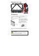
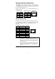
ATTENTION
Please DO NOT open or remove vent 12. Removing the seal will
void the warranty.
All exposed connectors, including 1 - 4, 6 - 9, should be tightly
covered by suitable caps when they are not in use.