
User Manual

- 4 -
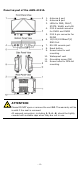
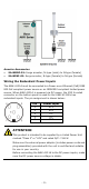
Panel Layout of the AWK-4131A
1. Antenna A port
2. Antenna B port
3. LEDs for PWR, FAULT,
STATE, WLAN, and LAN
4. M12 A-coded connector
for PWR1 and PWR2
5. M12 8-pin connector for
DI/DO
6. 10/100/1000BaseT(X)
RJ45 Port
7. RS-232 console port
8. Reset button
9. Screw holes for wall
mounting
10.
Waterproof vent
11.
Grounding screw (M4)
12.
Screw holes for DIN-rail
mounting
ATTENTION
Please DO NOT open or re
move the vent 10
. The warranty will be
invalid if the seal is removed.
All exposed connectors, including
1, 2, 4 - 8, should be tightly
covered with suitable caps when they are not in use.