
User Manual

- 10 -
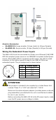
Wiring the Digital Inputs and Relay Contact (Digital
Output)
The AWK-4131A has two sets of digital input—DI1 and DI2. Each DI
comprises of two contacts of the 8-pin M12 connector on the
AWK-4131A’s bottom panel. These two digital inputs can be connected to
digital-output-enabled sensors for on-site status monitoring.
The AWK-4131A also has one relay output, which consists of the two
contacts. These relay contacts are used to detect user-configured events.
The two wires attached to the Relay contacts form an open circuit when a
user-configured event is triggered. If a user-configured event does not
occur, the Relay circuit will be closed.
A field-installable plug, M12A-8PMM-IP68, is recommended for
connecting the AWK-4131A’s DIs and relay.
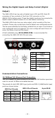
Communication Connections
10/100BaseT(X) Ethernet Port Connection
The 10/100BaseT(X) ports located on the AWK-4131A’s bottom panel are
used to connect to Ethernet-enabled devices.
The pinouts for both MDI (NIC-type) ports and MDI-X (HUB/Switch-type)
ports are shown below:
MDI Port Pinouts
MDI-X Port Pinouts
8-pin RJ45
Pin
Signal
1
Tx+
2
Tx-
3
Rx+
6
Rx-
Pin
Signal
1
Rx+
2
Rx-
3
Tx+
6
Tx-
Pin
Signal
1
Relay
2
3
DI1 I1
4
DI1 COM_1
5
DI2 I2
6
DI2 COM_2
7
Reserved
8