AWK-4131A Quick Installation Guide Moxa AirWorks Version 6.0, March 2019 Technical Support Contact Information www.moxa.
Table of Contents Overview ............................................................................... - 3 Hardware Setup .................................................................... - 3 Package Checklist ............................................................... - 3 Panel Layout of the AWK-4131A ........................................... - 4 Mounting Dimensions .......................................................... - 5 Attaching Antennas ...............................................
Overview The AWK-4131A IP68 outdoor industrial AP/bridge/client meets the growing need for faster data transmission speeds by supporting 802.11n technology and allowing 2X2 MIMO communication with a net data rate of up to 300 Mbps. The AWK-4131A is compliant with industrial standards and approvals covering operating temperature, power input voltage, surge, ESD, and vibration.
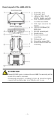
Panel Layout of the AWK-4131A 1. 2. 3. 4. 5. 6. 7. 8. 9. 10. 11. 12. Antenna A port Antenna B port LEDs for PWR, FAULT, STATE, WLAN, and LAN M12 A-coded connector for PWR1 and PWR2 M12 8-pin connector for DI/DO 10/100/1000BaseT(X) RJ45 Port RS-232 console port Reset button Screw holes for wall mounting Waterproof vent Grounding screw (M4) Screw holes for DIN-rail mounting ATTENTION Please DO NOT open or remove the vent 10. The warranty will be invalid if the seal is removed.
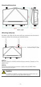
Mounting Dimensions Unit = mm Attaching Antennas By default, the AWK-4131A comes with two dual-band omni-directional antennas. Attach the antennas as illustrated below: STEP 1: Use your fingers to hold the antenna N-type connector (female) on the AWK-4131A. STEP 2: Screw the antenna N-type connector (male) onto the AWK-4131A device’s N-type connector. Caution For additional stability, hold the antenna connector when you screw on an antenna to the AWK-4131A device.
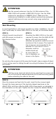
ATTENTION Use the correct antennas: Use the 2.4 GHz antenna if the AWK-4131A will operate in IEEE 802.11b/g/n. Use the 5GHz antenna for operations in IEEE802.11a/n. Make sure the antennas are installed in a safe outdoor area and are protected against lightning and surge current using surge protection systems. Wall Mounting In most applications, wall mount provides an easier installation. You will find it quite easy to mount AWK-4131A on the wall, as illustrated below.
ATTENTION To avoid environmental vibration or shock, you can consider a robust installation with four bigger screws, where the shafts are between 7.0 mm and 8.5 mm in diameter, and fix the AWK-4131A directly onto the wall and tighten the screws. DIN-Rail Mounting (Optional) The DK-DC50131 die-cast metal kit, which can be bought separately, enables easy and robust installation for the AWK-4131A. A pair of DK-DC50131s is needed to DIN-rail mount the AWK-4131A.
Deployment Precautions Wiring Requirements WARNING Safety First! Be sure to disconnect the power cord before installing and/or wiring your AWK-4131A. Calculate the maximum possible current in each power wire and common wire. Observe all electrical codes dictating the maximum current allowable for each wire size. If the current goes above the maximum ratings, the wiring could overheat, causing serious damage to your equipment.
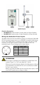
Arrester Accessories • • SA-NMNF-01: Surge arrester, N-type (male) to N-type (female) SA-NFNF-01: Surge arrester, N-type (female) to N-type (female) Wiring the Redundant Power Inputs The AWK-4131A must be connected to a Power-over-Ethernet (PoE) IEEE 802.3af compliant power source or an IEC60950 compliant limited power source. When AWK-4131A is powered via DC power, the M12 A-coded connector on the bottom panel is used for the AWK-4131A’s two redundant inputs.
Wiring the Digital Inputs and Relay Contact (Digital Output) The AWK-4131A has two sets of digital input—DI1 and DI2. Each DI comprises of two contacts of the 8-pin M12 connector on the AWK-4131A’s bottom panel. These two digital inputs can be connected to digital-output-enabled sensors for on-site status monitoring. The AWK-4131A also has one relay output, which consists of the two contacts. These relay contacts are used to detect user-configured events.
1000BaseT Ethernet Port Connection 1000BaseT data is transmitted on differential TRD+/- signal pairs over copper wires. MDI/MDI-X Port Pinouts Pin 1 2 3 4 5 6 7 8 Signal TRD(0)+ TRD(0)TRD(1)+ TRD(2)+ TRD(2)TRD(1)TRD(3)+ TRD(3)- RS-232 Connection The AWK-4131A has one RS-232 (8-pin RJ45) console port located on the bottom panel. Use either an RJ45-to-DB9 or RJ45-to-DB25 cable to connect the AWK-4131A’s console port to your PC’s COM port.
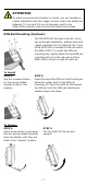
Waterproofing the RJ45 Plug Dimensions (unit: mm) Installation STEP 1: Attach the gasket ① to the housing ③ STEP 2: Insert the cable (e.g., CAT5e) through the clamp ring ④, screw nut ②, seal ⑤ and housing ③, as follows: STEP 3: Crimp the modular RJ plug to the cable. Note that the use of a snagless cover shield or a strain-relief boot is not recommended here.
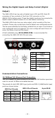
LED Indicators The front panel of the AWK-4131A contains several LED indicators. The function of each LED is described in the table below: LED PWR FAULT STATE WLAN LAN Color State Description Front Panel LED Indicators (System) Power is being supplied(from power On input 1 or 2, or PoE). Green Off Power is not being supplied. Cannot get an IP address from the Blinking DHCP server. (slow at 1-second intervals) Red Blinking (fast at IP address conflict. 0.
Specifications Input Current 0.64 A @ 12 VDC; 0.16 A @ 48 VDC Input Voltage Power Consumption 12 to 48 VDC, redundant dual DC power inputs or 48 VDC Power-over-Ethernet (IEEE 802.3af compliant) 7.68 W Operating Temperature -40 to 75°C (-40 to 167°F) Storage Temperature -40 to 85°C (-40 to 185°F) ATTENTION The AWK-4131A is NOT a portable mobile device and should be located 20 cm away from the human body. The AWK-4131A is NOT designed for the general public.
Software Setup This section covers the software setup of the AWK-4131A. How to Access the AWK Before installing the AWK device (AWK), make sure that all items in the package checklist are provided in the product box. You will also need access to a notebook computer or PC equipped with an Ethernet port. • Step 1: Select a suitable power source and plug in the AWK. The AWK can be powered by DC power ranging from 12 VDC to 48 VDC or by a PoE PSE via an Ethernet connection.
Point-to-Multipoint Scenario (AP/Client Mode) Configuring the AWK as an AP • Step 1: Set the operation mode of the AWK to AP mode. Go to Wireless LAN Setup Operation Mode and select AP. NOTE • The default operation mode for the AWK is AP. Step 2: Set up your own SSID. Go to Wireless LAN Setup WLAN Basic WLAN Setup and click Edit to set the SSID. NOTE The default SSID is MOXA.
• Step 3: Set the RF type and Channel for the AWK. Go to Wireless LAN Setup WLAN Basic WLAN Setup. We recommend that you choose the RF type 5 GHz for a relative clean medium with minimum interference. For the Channel setting, we recommend that you choose a channel other than the default channel to avoid interference. Click Submit to apply the changes, and restart the AWK in AP mode to complete the configuration process.
• Step 3: Set the RF type and Channel settings for the AWK. On the Wireless LAN Setup WLAN Basic WLAN Setup page, edit the RF type and Channel settings. Click Submit to apply the changes, and restart the AWK in client mode to complete the configuration process. Point-to-Point Scenario (Master/slave mode) Configuring the AWK as a Master • Step 1: Set the operation mode of the AWK to Master mode.
Configuring the AWK as a Slave • Step 1: Set the operation mode of the AWK to Slave mode. Go to Wireless LAN Setup Operation Mode, set the operation mode to Slave, and then click Submit to apply the change. • Step 2: Link to an existing SSID. Go to Wireless LAN Setup WLAN Basic WLAN Setup and click Site Survey to select an existing SSID, or directly enter an existing SSID in the text field. • Step 3: Set the RF type for the AWK.