
User Manual

- 9 -
Arrester Accessories
• SA-NMNF-01: Surge arrester, N-type (male) to N-type (female)
• SA-NFNF-01: Surge arrester, N-type (female) to N-type (female)
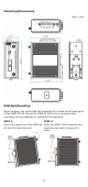
Wiring the Redundant Power Inputs
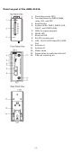
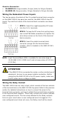
The top two pairs of contacts of the 10-contact terminal block connector
on the AWK-3131A’s top panel are used for the AWK-3131A’s two DC
inputs. Top and front views of the terminal block connector are shown
below.
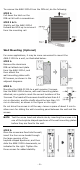
STEP 1: Insert the negative/positive DC wires
into the
V-/V+ terminals.
STEP 2:
To keep the DC wires from pulling
loose,
use a small flat
-
blade screwdriver to tighten the
wire
-clamp screws on the front of the terminal
block connector.
STEP 3:
Insert the plastic terminal block
connector prongs into the terminal block
receptor, which is
located on the AWK-3131A’s
t
op panel.
NOTE
Input Terminal Block (CN1) is suitable for wire size range of
12
-28 AWG (3.31-0.0804 mm²) and a torque value of 4.5 lb-in
(0.51 Nm).
ATTENTION
If the AWK
-
3131A is connected to a motor or other similar type of
equipment, be sure to use power isolation protection. Before
connecting the
AWK-3131A to the DC power inputs, make sure
the DC power source voltage is stable.
Wiring the Relay Contact
The AWK-3131A has one relay output, which consists of the two contacts
of the terminal block on the AWK-3131A’s top panel. Refer to the previous
section for detailed instructions on how to connect the wires to the
terminal block connector, and how to attach the terminal block connector
to the terminal block receptor. These relay contacts are used to indicate
user-configured events. The two wires attached to the Relay contacts
form an open circuit when a user-configured event is triggered. If a
user-configured event does not occur, the Relay circuit will be closed.