
User Manual

- 4 -
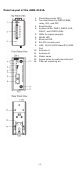
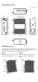
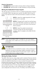
Panel Layout of the AWK-3131A
1. Grounding screw (M5)
2. Terminal block for PWR1,PWR2,
relay, DI1, and DI2
3. Reset button
4. System LEDs: PWR1, PWR2, PoE,
FAULT, and STATE LEDs
5. LEDs for signal strength
6. WLAN LED
7. Ethernet LED
8. RS-232 console port
9. LAN: 10/100/1000 BaseT(X) RJ45
Port
10.
Antenna A
11.
Antenna B
12.
Model name
13.
Screw holes for wall-mounting kit
14.
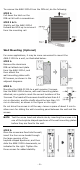
DIN-rail mounting kit