
User Manual

- 10 -
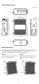
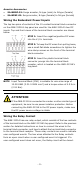
Wiring the Digital Inputs
The AWK-3131A has two sets of digital inputs—DI1 and DI2. Each DI
comprises two contacts of the 10-pin terminal block connector on the
AWK-3131A’s top panel. Refer to the “Wiring the Redundant Power Inputs”
section for detailed instructions on how to connect the wires to the
terminal block connector, and how to attach the terminal block connector
to the terminal block receptor.
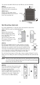
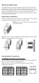
Cable Holder Installation
Attach the cable holder to the bottom of the AWK-3131A to keep cabling
neat and avoid accidents that result from untidy cables.
STEP 1: Screw the cable holder onto the bottom
of the AWK
-3131A.
STEP 2:
After mounting the AWK-
3131A and plugging in the LAN cable,
tighten the cable along the device and wall.
Communication Connections
10/100BaseT(X) Ethernet Port Connection
The 10/100BaseT(X) ports located on the AWK-3131A’s front panel are
used to connect to Ethernet-enabled devices.
Below we show pinouts for both MDI (NIC-type) ports and MDI-X
(HUB/switch-type) ports.
MDI Port Pinouts
MDI-X Port Pinouts
8-pin RJ45
Pin
Signal
1
Tx+
2
Tx-
3
Rx+
6
Rx-
Pin
Signal
1
Rx+
2
Rx-
3
Tx+
6
Tx-