AWK-3131A Quick Installation Guide Moxa AirWorks Edition 8.0, May 2018 Technical Support Contact Information www.moxa.
Table of Contents Overview ............................................................................... - 3 Hardware Setup .................................................................... - 3 Package Checklist ............................................................... - 3 Panel Layout of the AWK-3131A ........................................... - 4 Mounting Dimensions .......................................................... - 5 DIN-Rail Mounting ................................................
Overview The AWK-3131A 3-in-1 industrial wireless access point meets the growing need for faster data transmission speeds and wider coverage by supporting IEEE 802.11n technology with a net data rate of up to 300 Mbps. The AWK-3131A combines two adjacent 20 MHz channels into a single 40 MHz channel to deliver a potent combination of greater reliability and more bandwidth.
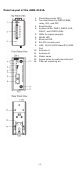
Panel Layout of the AWK-3131A 1. 2. 3. 4. 5. 6. 7. 8. 9. 10. 11. 12. 13. 14.
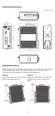
Mounting Dimensions Unit = mm DIN-Rail Mounting When shipped, the metal DIN-rail mounting kit is fixed to the back panel of the AWK-3131A. Mount the AWK-3131A on to a corrosion-free mounting rail that adheres to the EN 60715 standard. STEP 1: STEP 2: Insert the upper lip of the DIN-rail Press the AWK-3131A towards the kit into the mounting rail. mounting rail until it snaps into place.
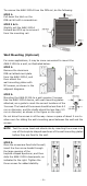
To remove the AWK-3131A from the DIN rail, do the following: STEP 1: Pull down the latch on the DIN-rail kit with a screwdriver. STEP 2 & 3: Slightly pull the AWK-3131A forward and lift it up to remove it from the mounting rail. Wall Mounting (Optional) For some applications, it may be more convenient to mount the AWK-3131A to a wall, as illustrated below.
WARNING • • • • This equipment is intended to be used in a Restricted Access Location, such as a dedicated computer room where only authorized service personnel or users can gain access. Such personnel must be instructed about the fact that the metal chassis of the equipment is extremely hot and may cause burns. Service personnel or users have to pay special attention and take special precautions before handling this equipment.
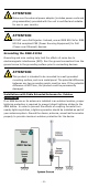
ATTENTION Make sure the external power adapter (includes power cords and plug assemblies) provided with the unit is certified and suitable for use in your country. ATTENTION DO NOT use a PoE Injector. Instead, use an IEEE 802.3af or IEEE 802.3at compliant PSE (Power Sourcing Equipment) for PoE (Power over Ethernet) devices. Grounding the AWK-3131A Grounding and wire routing help limit the effects of noise due to electromagnetic interference (EMI).
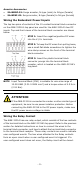
Arrester Accessories • • SA-NMNF-01: Surge arrester, N-type (male) to N-type (female) SA-NFNF-01: Surge arrester, N-type (female) to N-type (female) Wiring the Redundant Power Inputs The top two pairs of contacts of the 10-contact terminal block connector on the AWK-3131A’s top panel are used for the AWK-3131A’s two DC inputs. Top and front views of the terminal block connector are shown below. STEP 1: Insert the negative/positive DC wires into the V-/V+ terminals.
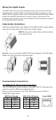
Wiring the Digital Inputs The AWK-3131A has two sets of digital inputs—DI1 and DI2. Each DI comprises two contacts of the 10-pin terminal block connector on the AWK-3131A’s top panel. Refer to the “Wiring the Redundant Power Inputs” section for detailed instructions on how to connect the wires to the terminal block connector, and how to attach the terminal block connector to the terminal block receptor.
1000BaseT Ethernet Port Connection 1000BaseT data is transmitted on differential TRD+/- signal pairs over copper wires. MDI/MDI-X Port Pinouts Pin 1 2 3 4 5 6 7 8 Signal TRD(0)+ TRD(0)TRD(1)+ TRD(2)+ TRD(2)TRD(1)TRD(3)+ TRD(3)- RS-232 Connection The AWK-3131A has one RS-232 (8-pin RJ45) console port located on the front panel. Use either an RJ45-to-DB9 or RJ45-to-DB25 cable to connect the AWK-3131A’s console port to your PC’s COM port.
LED Indicators The front panel of the AWK-3131A contains several LED indicators. The function of each LED is described in the table below: LED Color State Description Front Panel LED Indicators (System) On Power is on (power input 1) PWR1 Green Off Power is not being supplied. On Power is on (power input 2) PWR2 Green Off Power is not being supplied. On Power is being supplied via the PoE. PoE Amber Off Power is not being supplied via PoE.
LED Color Green State On Blinking Off On Amber Blinking LAN Off Description LAN port’s 1000 Mbps link is active. Data is being transmitted at 1000 Mbps. LAN port’s 1000 Mbps link is inactive. LAN port’s 10/100 Mbps link is active. Data is being transmitted at 10/100 Mbps. LAN port’s 10/100 Mbps link is inactive. Specifications Input Current Input Voltage Power Consumption Operating Temperature Storage Temperature 0.6 A @ 12 VDC; 0.
ATTENTION Do not locate the antenna near overhead power lines or other electric light or power circuits, or where it can come into contact with such circuits. When installing the antenna, take extreme care not to come into contact with such circuits, because they may cause serious injury or death. For proper installation and grounding of the antenna, refer to national and local codes (for example, U.S.: NFPA 70; National Electrical Code (NEC) Article 810; Canada: Canadian Electrical Code, Section 54).
WARNING EXPLOSION HAZARD Substitution of any component may impair suitability for Class I, Division 2. Software Setup This section covers the software setup for the AWK-3131A. How to Access the AWK Before installing the AWK device (AWK), make sure that all items in the package checklist are provided in the product box. You will also need access to a notebook computer or PC equipped with an Ethernet port. • Step 1: Select a suitable power source and plug in the AWK.
First-Time Quick Configuration After successfully accessing the AWK, refer to the appropriate subsection below to quickly set up a wireless network. NOTE Ensure that there are no IP address conflicts when you configure more than one AWK on the same subnet. Point-to-Multipoint Scenario (AP/Client Mode) Configuring the AWK as an AP • Step 1: Set the operation mode of the AWK to AP mode. Go to Wireless LAN Setup Operation Mode and select AP. NOTE • The default operation mode for the AWK is AP.
• Step 3: Set the RF type and Channel for the AWK. Go to Wireless LAN Setup WLAN Basic WLAN Setup. We recommend that you choose the RF type 5 GHz for a relative clean medium with minimum interference. For the Channel setting, we recommend that you choose a channel other than the default channel to avoid interference. Click Submit to apply the changes, and restart the AWK in AP mode to complete the configuration process.
• Step 3: Set the RF type and Channel settings for the AWK. On the Wireless LAN Setup WLAN Basic WLAN Setup page, edit the RF type and Channel settings. Click Submit to apply the changes, and restart the AWK in client mode to complete the configuration process. Point-to-Point Scenario (Master/slave mode) Configuring the AWK as a Master • Step 1: Set the operation mode of the AWK to Master mode.
Configuring the AWK as a Slave • Step 1: Set the operation mode of the AWK to Slave mode. Go to Wireless LAN Setup Operation Mode, set the operation mode to Slave, and then click Submit to apply the change. • Step 2: Link to an existing SSID. Go to Wireless LAN Setup WLAN Basic WLAN Setup and click Site Survey to select an existing SSID, or directly enter an existing SSID in the text field. • Step 3: Set the RF type for the AWK.