
Installation guide


- 12 -
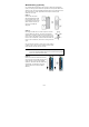
NOTE 1. The pin numbers for male DB9 and DB25 connectors, and
hole numbers for female DB9 and DB25 connectors are
labeled on the connector. However, the numbers are
typically quite small, so you may need to use a magnifying
glass to see the numbers clearly.
2. The pin numbers for both 8-pin and 10-
pin RJ45 connectors
(and ports) are typically not labeled on the connector (or
port). Refer to the Pinout diagram above to see how RJ45
pins are numbered.
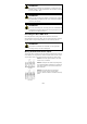
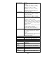
LED Indicators
The front panel of the Moxa AWK-3131 contains several LED indicators.
The function of each LED is described in the table below.
LED Color State Description
Front Panel LED Indicators (System)
PWR1 Green
On
Power is being supplied from power
input 1.
Off
Power is not being supplied from
power input 1.
PWR2 Green
On
Power is being supplied from power
input 2.
Off
Power is not being supplied from
power input 2.
PoE Amber
On Power is being supplied via PoE.
Off Power is not being supplied via PoE.
FAULT Red
Blink
(slow)
Cannot get an IP address from the
DHCP server (interval: 1 sec)
Blink
(fast)
IP address conflict (interval: 0.5 sec)
Off Error condition does not exist.
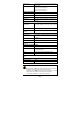
STATE
Green/
Red
Green
Software Ready
Green
Blink
The AWK has been located by AWK
Search Utility. (interval: 1sec)
Red Booting error condition
SIGNAL
(5 LEDs)
Green
On Signal level
(for Client/Slave mode only)
Off
WLAN
Green/
Amber
Amber
On
WLAN functions in AP/Bridge mode.
Amber
Blink
WLAN’s data communication is run in
AP/Bridge mode
Off
WLAN is not in use or not working
properly
Green On
WLAN functions in Client/Slave mode.
Green
Blink
WLAN’s data communication is run in
Client/Slave mode