AWK-3131 Hardware Installation Guide Moxa AirWorks First Edition, February 2011 2011 Moxa Inc. All rights reserved.
Overview Moxa's new AWK-3131 3-in-1 industrial wireless AP/bridge/client meets the growing need for faster data transmission speeds and wider coverage by supporting IEEE 802.11n technology with a net data rate of up to 300 Mbps. The AWK-3131 combines two adjacent 20 MHz channels into a single 40 MHz channel to deliver a potent combination of greater reliability and more bandwidth.
• • • • • • SFP-1GLHXLC: Small form factor pluggable transceiver with 1000BaseLHX, LC, 40 km, 0 to 60°C SFP-1GLHXLC-T: Small form factor pluggable transceiver with 1000BaseLHX, LC, 40 km, -40 to 85°C SFP-1GZXLC: Small form factor pluggable transceiver with 1000BaseZX, LC, 80 km, 0 to 60°C SFP-1GZXLC-T: Small form factor pluggable transceiver with 1000BaseZX, LC, 80 km, -40 to 85°C SFP-1GEZXLC: Small form factor pluggable transceiver with 1000BaseEZX, LC, 110 km, 0 to 60°C SFP-1GEZXLC-120: Small form f
ATTENTION For security reasons, we strongly recommend changing the password. To do so, select Maintenance Password, and then follow the on-screen instructions. Step 5: Select the operation mode for the AWK-3131 By default, the AWK-3131’s operation mode is set to AP. You can change the setting in Wireless Settings Basic Wireless Settings if you would like to use the Client mode.
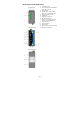
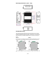
Panel Layout of the AWK-3131 1. 2. 3. 4. 5. 6. 7. 8. 9. 10. 11. 12. 13. 14.
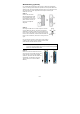
Mounting Dimensions (unit = mm) DIN-Rail Mounting The aluminum DIN-Rail attachment plate should be fixed to the back panel of the AWK-3131 when you take it out of the box. If you need to reattach the DIN-Rail attachment plate to the AWK-3131, make sure the stiff metal spring is situated towards the top, as shown in the figures below. STEP 1: STEP 2: Insert the top of the DIN-Rail into theThe DIN-Rail attachment unit will slot just below the stiff metal spring. snap into place as shown below.
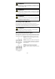
Wall Mounting (optional) For transportation applications that require an EN 50155 certification report, we strongly recommend the purchase of the optional AWK-3131 wallmount kit, which has passed EN 50155 testing. This wallmount kit is also convenient for other applications that require mounting the AWK-3131 to a wall. STEP 1: Remove the aluminum DIN-Rail attachment plate from the AWK-3131, and then attach the wall mount plates with M3 screws, as shown in the adjacent diagrams.
WARNING • • • • This equipment is intended to be used in a Restricted Access Location, such as a dedicated computer room. Access can only be gained by SERVICE PERSONS or by USERS who have been instructed about the fact that the metal chassis of the equipment is extremely hot and may cause burns. Service persons or users have to pay special attention and take special precaution before handling the equipment.
ATTENTION This product is intended to be supplied by a Listed Power Unit marked “Class 2” or “LPS” and rated O/P: 12 to 48 VDC, minimum 6 W (12 V to 48V), 25°C. ATTENTION Make sure the external power adaptor (includes power cords and plug assemblies) provided with the unit is certified and suitable for use in your country. ATTENTION Do not use the PoE Injector. Instead, please use an IEEE802.3af or IEEE802.3at compliant PSE (Power Sourcing Equipment) for PoE (Power over Ethernet) device.
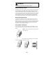
ATTENTION Before connecting the AWK-3131 to the DC power inputs, make sure the DC power source voltage is stable. Wiring the Relay Contact The AWK-3131 has one relay output, which consists of the two contacts of the terminal block on the AWK-3131’s top panel. Refer to the previous section for detailed instructions on how to connect the wires to the terminal block connector, and how to attach the terminal block connector to the terminal block receptor.
Communication Connections 10/100BaseT(X) Ethernet Port Connection The 10/100BaseT(X) ports located on the AWK-3131’s front panel are used to connect to Ethernet-enabled devices. Below we show pinouts for both MDI (NIC-type) ports and MDI-X (HUB/Switch-type) ports. MDI Port Pinouts Pin Signal 1 Tx+ 2 Tx3 Rx+ 6 Rx- MDI-X Port Pinouts Pin Signal 1 Rx+ 2 Rx3 Tx+ 6 Tx- 8-pin RJ45 1000BaseT Ethernet Port Connection 1000BaseT data is transmitted on differential TRD+/- signal pairs over copper wires.
NOTE 1. 2. The pin numbers for male DB9 and DB25 connectors, and hole numbers for female DB9 and DB25 connectors are labeled on the connector. However, the numbers are typically quite small, so you may need to use a magnifying glass to see the numbers clearly. The pin numbers for both 8-pin and 10-pin RJ45 connectors (and ports) are typically not labeled on the connector (or port). Refer to the Pinout diagram above to see how RJ45 pins are numbered.
LAN Green/ Amber Amber Amber Blinking Amber Off Green Green Blinking Green Off LAN port’s 10/100 Mbps link is active. Data is being transmitted at 10/100 Mbps LAN port’s 10/100 Mbps link is inactive LAN port’s 1000 Mbps link is active. Data is being transmitted at 1000 Mbps LAN port’s 1000 Mbps link is inactive Specifications WLAN Interface Standards: Spread Spectrum and Modulation (typical): Operating Channels (central frequency): Security: Transmission Rates: IEEE 802.
TX Transmit Power: TX Transmit Power MIMO: RX Sensitivity: RX Sensitivity MIMO: 802.11b: 1 to 11 Mbps: Typ. 18 dBm (± 1.5 dBm) 802.11g: 6 to 24 Mbps: Typ. 18 dBm (± 1.5 dBm) 36 to 48 Mbps: Typ. 17 dBm (± 1.5 dBm) 54 Mbps: Typ. 15 dBm (± 1.5 dBm) 802.11a: 6 to 24 Mbps: Typ. 17 dBm (± 1.5 dBm) 36 to 48 Mbps: Typ. 16 dBm (± 1.5 dBm) 54 Mbps: Typ. 14 dBm (± 1.5 dBm) 802.11a/n (20/40 MHz): MCS15 20 MHz: Typ. 13 dBm (± 1.5 dBm) MCS15 40 MHz: Typ. 12 dBm (± 1.5 dBm) 802.11g/n (20/40 MHz): MCS15 20 MHz: Typ.
Alarm Contact: Digital Inputs: 1 relay output with current carrying capacity of 1 A @ 24 VDC 2 electrically isolated inputs • +13 to +30 V for state “1” • +3 to -30 V for state “0” • Max. input current: 8 mA Physical Characteristics Housing: Metal, IP30 protection Weight: 970 g Dimensions: 53.6 x 135 x 105 mm (2.11 x 5.31 x 4.13 in) Installation: DIN-Rail mounting (standard), wall mounting (optional) Environmental Limits Operating Temperature: Standard Models: 0 to 60°C (32 to 140°F) Wide Temp.
ATTENTION Use the antennas correctly: The 2.4 GHz antennas are needed when the AWK-3131 operates in IEEE 802.11b/g/n. The 5 GHz antennas are needed for IEEE802.11a/n. Make sure your antenna installation is within a safety area, which is covered by a lightning protection or surge arrest system. Technical Support Contact Information www.moxa.