
Installation Guide
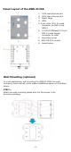


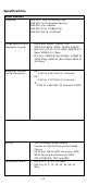
Table Of Contents

- 8 -
ATTE
NTION
Be
fore connecting the AWK-3121B to the DC power inputs,
make
sure
the
DC power source voltage is stable.
Co
mmunication Connections
10/10
0/1000BaseT(X) Ethernet Port Connection
The AWK-3121B has a 10/100/1
0
00BaseT(X) Ethernet port (LAN1 8-
pin shielded
M12
X-coded
connector).
The
10/100/1000TX
port
located
on
the
front
panel
is
used
to
connect
to
Ethernet-enabled
devices.
Most
users
configure
this
port
for
Auto
MDI/MDI-X
mode,
in
which
case
the
port’s
pinouts
are
adjusted
automatically
depending
on
the
type
of
Ethernet
cable
used
(straight-through
or
cross-over), and
the
type
of
device
(NIC-type
or
HUB/Switch-type)
connected
to
the
port.
Pinouts
for
the
10/100/1000BaseT(X)
(M12
8-pin female
X-
coded)
port
Pin
No.
GbE
Conn.
FE Conn.
1
DA+
TD+
2
DA-
TD-
3
DB+
R
D+
4
DB-
RD-
5 DD+ –
6 DD- –
7 DC-
–
8 DC+
–
Gr
ounding the Moxa AWK-3121B
Gr
ounding and wire routing help limit the effects of noise due to
electromagnetic interference (EMI). Run the ground connection from
the ground screw to the grounding surface prior to connecting devices.
Connecting the Power Supplies
The AWK-3121B su
p
p
orts two types of power supplies— PWR1 and
PWR2. The 4-pin male M12 A-coded connector on the AWK-3121B front
panel is used for the dual power inputs. You can use the metal M12
male 4-pin A-coded screw-type crimp circular connector with pins for
power connection included with the product or purchase the
M12 power cable (optional) CBL-M12(FF4P)/Open-BK-100-IP68 for lab
use/tests.
Pinouts for the power input (4-pin male M12 A-coded) port:
Pin No.
Power
Input
1 V1+
2 V2+
3 V1-
4 V2-
ATTENTIO
N
Th
is product is intended to be mounted to a well-grounded
mounting surface, such as a metal panel.