
Installation Guide
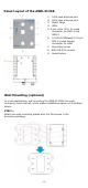


Table Of Contents

- 4 -
Pan
el Layout of the AWK-3121B
1. 1A N-typ
e antenna port
2. 1B N-type antenna port
3. Model name
4. LEDs
5. 4-pin male M12 A-coded
connector for PWR-1
and
PWR-2
6. 10/100/1000BaseT(X) 8-pin
M12 X-coded
female
connector
for LAN1
7. Grounding screw
8. RJ45 RS-232 console
Reset button9.
Wal
l Mounting (optional)
In mo
st applications, wall mounting the AWK-3121Bis the most
commonly used method, which makes installation easier as illustrated
below:
STEP 1:
Attach the wall-mounting plates with the M4 screws in the
accessory package.