
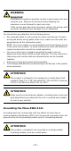
Installation guide


- 4 -
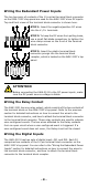
the first AWK-3121 connected to notebook A, and change the second or
third AWK-3121 connected to notebook B to Client mode and then
configure the notebooks and AWK-3121s properly.
After setting up the testing environment, open a DOS window on
notebook B. At the prompt, type
ping IP address of notebook A
and then press Enter key. A “Reply from IP address …” response means
the communication was successful. A “Request timed out.” response
means the communication failed. In this case, recheck the configuration
to make sure the connections are correct.
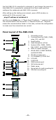
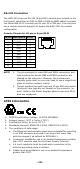
Panel Layout of the AWK-3121
1. Grounding screw
2.
Terminal block for PWR1, PWR2,
relay, DI1, and DI2
3. Reset button
4. Heat dissipation orifices
5. System LEDs: PWR1, PWR2,
PoE, FAULT, and STATE LEDs
6. LEDs for signal strength
7. WLAN LEDs: CLIENT BRIDGE,
and WLAN LEDs
8. RS-232 console port
9. 10/100BaseT(X) RJ45 Port
10.
10M LED
11.
100M LED
12.
MAIN antenna port
13.
AUX antenna port
14.
Model name
15.
Screw hole for wall mounting kit
16.
DIN-Rail mounting kit