AWK-3121 Quick Installation Guide Moxa AirWorks Fifth Edition, March 2012 2012 Moxa Inc. All rights reserved. Reproduction without permission is prohibited.
Overview Moxa’s AWK-3121 Access Point/Bridge/AP Client is ideal for applications that are hard to wire, too expensive to wire, or use mobile equipment that connects over a TCP/IP network. The AWK-3121 is rated to operate at temperatures ranging from -25 to 60°C for standard models and -40 to 75°C for extended temperature models, and is rugged enough for any harsh industrial environment. Installation is easy, with either DIN-Rail mounting or distribution boxes.
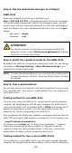
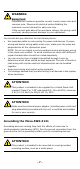
Step 4: Use the web-based manager to configure AWK-3121 Open your computer’s web browser and then type http://192.168.127.253 in the address field to access the homepage of the web-based management. Before the homepage opens, you will need to enter the user name and password. For first-time configuration, enter the default user name and password and then click on the Login button: User name: Password: admin root ATTENTION For security reasons, we strongly recommend changing the password.
the first AWK-3121 connected to notebook A, and change the second or third AWK-3121 connected to notebook B to Client mode and then configure the notebooks and AWK-3121s properly. After setting up the testing environment, open a DOS window on notebook B. At the prompt, type ping IP address of notebook A and then press Enter key. A “Reply from IP address …” response means the communication was successful. A “Request timed out.” response means the communication failed.
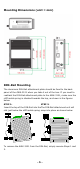
Mounting Dimensions (unit = mm) DIN-Rail Mounting The aluminum DIN-Rail attachment plate should be fixed to the back panel of the AWK-3121 when you take it out of the box. If you need to reattach the DIN-Rail attachment plate to the AWK-3121, make sure the stiff metal spring is situated towards the top, as shown in the figures below. STEP 1: STEP 2: Insert the top of the DIN-Rail into theThe DIN-Rail attachment unit will slot just below the stiff metal spring. snap into place as shown below.
Wall Mounting (optional) For some applications, it may be more convenient to mount the AWK-3121 to a wall, as illustrated below. STEP 1: Remove the aluminum DIN-Rail attachment plate from the AWK-3121, and then attach the wall mount plates with M3 screws, as shown in the adjacent diagrams. ⇒ STEP 2: Mounting the AWK-3121 to a wall requires 4 screws. Use the AWK-3121 device, with wall mount plates attached, as a guide to mark the correct locations of the 4 screws.
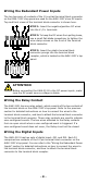
WARNING Safety First! Calculate the maximum possible current in each power wire and common wire. Observe all electrical codes dictating the maximum current allowed for each wire size. If the current goes above the maximum ratings, the wiring could overheat, causing serious damage to your equipment. You should also pay attention to the following items: • • • • Use separate paths to route wiring for power and devices.
Wiring the Redundant Power Inputs The top two pairs of contacts of the 10-contact terminal block connector on the AWK-3121’s top panel are used for the AWK-3121’s two DC inputs. Top and front views of the terminal block connector is shown here. STEP 1: Insert the negative/positive DC wires into the V-/V+ terminals. STEP 2: To keep the DC wires from pulling loose, use a small flat-blade screwdriver to tighten the wire-clamp screws on the front of the terminal block connector.
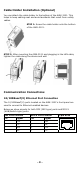
Cable Holder Installation (Optional) You can attach the cable holder to the bottom of the AWK-3121. This helps to keep cabling neat and avoid accidents that result from untidy cables. STEP 1: Screw the cable holder onto the bottom of the AWK-3121. STEP 2: After mounting the AWK-3121 and plugging in the LAN cable, tighten the cable along the device and wall.
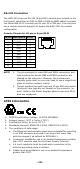
RS-232 Connection The AWK-3121 has one RS-232 (8-pin RJ45) console port located on the front panel. Use either an RJ45-to-DB9 or RJ45-to-DB25 cable to connect the Moxa AWK-3121’s console port to your PC’s COM port. You may then use a console terminal program to access the AWK-3121 for console configuration. Console Pinouts for 10-pin or 8-pin RJ45 10-Pin Description 1 ----2 DSR 3 RTS 4 GND 5 TxD 6 RxD 7 DCD 8 CTS 9 DTR 10 ----NOTE 1. 2.
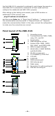
ATTENTION For railway rolling stock applications, AWK-3121 devices must use a galvanically isolated power supply that is compliant with the EN 50155 standard. LED Indicators The front panel of the Moxa AWK-3121 contains several LED indicators. The function of each LED is described in the table below. LED Color State Description Front Panel LED Indicators (System) Power is being supplied from power On input 1. PWR1 Green Power is not being supplied from Off power input 1.
Specifications WLAN Interface Standards: IEEE 802.11a/b/g for Wireless LAN IEEE 802.11i for Wireless Security IEEE 802.3 for 10BaseT IEEE 802.3u for 100BaseTX IEEE 802.3af for Power-over-Ethernet IEEE 802.1D for Spanning Tree Protocol IEEE 802.1w for Rapid STP Spread Spectrum and Modulation (typical): • DSSS with DBPSK, DQPSK, CCK • OFDM with BPSK, QPSK, 16QAM, 64QAM • 802.11b: CCK @ 11/5.5 Mbps, DQPSK @ 2 Mbps, DBPSK @ 11 Mbps • 802.
RX Sensitivity: 802.11b: -97 dBm @ 1 Mbps, -94 dBm @ 2 Mbps, -92 dBm @ 5.5 Mbps, -90 dBm @ 11 Mbps 802.11g: -93 dBm @ 6 Mbps, -91 dBm @ 9 Mbps, -90 dBm @ 12 Mbps, -88 dBm @ 18 Mbps, -84 dBm @ 24 Mbps, -80 dBm @ 36 Mbps, -76 dBm @ 48 Mbps, -74 dBm @ 54 Mbps 802.
Storage Temperature: -40 to 85°C (-40 to 185°F) Ambient Relative Humidity: 5% to 95% (non-condensing) Power Requirements Input Voltage: 12 to 48 VDC, redundant dual DC power inputs or 48 VDC Power-over-Ethernet (IEEE 802.3af compliant)* *Compliant with EN 50155 on 24 VDC *PoE is only available for the AWK-3121 and AWK-3121-M12 Connector: 10-pin removable terminal block Power Consumption: 12 to 48 VDC, 0.121 to 0.
Technical Support Contact Information www.moxa.