
User Manual

- 9 -
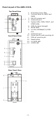
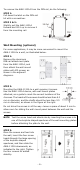
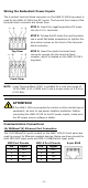
Wiring the Redundant Power Inputs
The 4-contact terminal block connector on the AWK-1131A’s top panel is
used for the AWK-1131A’s two DC inputs. The top and front views of the
terminal block connector are shown here.
Top View
Front View
STEP 1: Insert the negative/positive DC wires
into the
V-/V+ terminals.
STEP 2:
To keep the DC wires from pulling
loose,
use a small flat
-
blade screwdriver to tighten the
wire
-clamp screws on the front of the terminal
block connector.
STEP 3:
Insert the plastic terminal block
connector prongs into the terminal block
receptor, which is
located on the AWK-1131A’s
t
op panel.
NOTE
Input Terminal Block (CN1) is suitable for a wire size range of
12
-28 AWG (3.31-0.0804 mm²) and a torque value of 4.5 lb-in
(0.51 Nm).
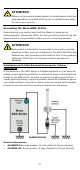
ATTENTION
If the AWK
-
1131A is connected to a motor or other similar type of
equipment, be sure to use power isolation protection. Before
connecting the AWK
-1131A to the DC power inputs, make sure
the DC power source voltage is stable.
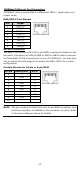
Communication Connections
10/100BaseT(X) Ethernet Port Connection
The 10/100BaseT(X) ports located on the AWK-1131A’s front panel are
used to connect to Ethernet-enabled devices. Below we show pinouts for
both MDI (NIC-type) ports and MDI-X (HUB/Switch-type) ports.
MDI Port Pinouts
MDI-X Port Pinouts
8-pin RJ45
Pin
Signal
1
Tx+
2
Tx-
3
Rx+
6
Rx-
Pin
Signal
1
Rx+
2
Rx-
3
Tx+
6
Tx-