AWK-1131A Quick Installation Guide Moxa AirWorks Edition 8.0, July 2018 Technical Support Contact Information www.moxa.
Table of Contents Overview ............................................................................... - 3 Hardware Setup .................................................................... - 3 Package Checklist ............................................................... - 3 Panel Layout of the AWK-1131A ........................................... - 4 Mounting Dimensions .......................................................... - 5 DIN-Rail Mounting ................................................
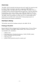
Overview The AWK-1131A industrial wireless access point meets the growing need for faster data transmission speeds by supporting IEEE 802.11n technology with a net data rate of up to 300 Mbps. The AWK-1131A is compliant with the industrial standards and approvals, covering operating temperature, power input voltage, surge, ESD and vibration. The two redundant DC power inputs increase the reliability of the power supply. The AWK-1131A can operate on either the 2.
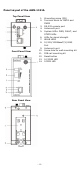
Panel Layout of the AWK-1131A Top Panel View 1. 2. 3. 4. 5. 6. 7. 8. Front Panel View 9. 10. 11. 12. 13. 14.
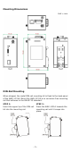
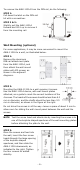
Mounting Dimensions Unit = mm DIN-Rail Mounting When shipped, the metal DIN-rail mounting kit is fixed to the back panel of the AWK-1131A. Mount the AWK-1131A on a corrosion-free mounting rail that adheres to the EN 60715 standard. STEP 1: Insert the upper lip of the DIN-rail kit into the mounting rail. STEP 2: Press the AWK-1131A towards the mounting rail until it snaps into place.
To remove the AWK-1131A from the DIN rail, do the following: STEP 1: Pull down the latch on the DIN-rail kit with a screwdriver. STEP 2 & 3: Slightly pull the AWK-1131A forward and lift it up to remove it from the mounting rail. Wall Mounting (optional) For some applications, it may be more convenient to mount the AWK-1131A to a wall, as illustrated below.
WARNING • • • • This equipment is intended to be used in a Restricted Access Location, such as a dedicated computer room where only authorized service personnel or users can gain access. Such personnel must be instructed about the fact that the metal chassis of the equipment is extremely hot and may cause burns. Service personnel or users have to pay special attention and take special precautions before handling this equipment.
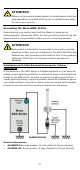
ATTENTION Make sure the external power adaptor (includes power cords and plug assemblies) provided with the unit is certified and suitable for use in your country. Grounding the Moxa AWK-1131A Grounding and wire routing help limit the effects of noise due to electromagnetic interference (EMI). Run the ground connection from the ground screw to the grounding surface prior to connecting devices. ATTENTION This product is intended to be mounted on to a well-grounded mounting surface, such as a metal panel.
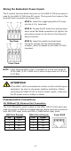
Wiring the Redundant Power Inputs The 4-contact terminal block connector on the AWK-1131A’s top panel is used for the AWK-1131A’s two DC inputs. The top and front views of the terminal block connector are shown here. STEP 1: Insert the negative/positive DC wires into the V-/V+ terminals. STEP 2: To keep the DC wires from pulling loose, use a small flat-blade screwdriver to tighten the wire-clamp screws on the front of the terminal block connector.
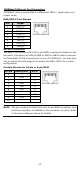
00BaseT Ethernet Port Connection 1000BaseT data is transmitted on differential TRD+/- signal pairs over copper wires. MDI/MDI-X Port Pinouts Pin 1 2 3 4 5 6 7 8 Signal TRD(0)+ TRD(0)TRD(1)+ TRD(2)+ TRD(2)TRD(1)TRD(3)+ TRD(3)- RS-232 Connection The AWK-1131A has one RS-232 (8-pin RJ45) console port located on the top panel. Use either an RJ45-to-DB9 or RJ45-to-DB25 cable to connect the Moxa AWK-1131A’s console port to your PC’s COM port.
LED Indicators The front panel of the Moxa AWK-1131A contains several LED indicators. The function of each LED is described in the table below. LED Color State Description Front Panel LED Indicators (System) On Power is on. PWR Green Off Power is not being supplied. Blinking (fast at Cannot get an IP address from the 0.5-second DHCP server. intervals) FAULT Red Blinking (slow at IP address conflict. 1-second intervals) Off Error condition does not exist.
Specifications Input Current Input Voltage Power Consumption Operating Temperature Storage Temperature 0.56 A @ 12 VDC, 0.14 A @ 48 VDC 12 to 48 VDC, redundant dual DC power inputs 6.96 W Standard Models: 0 to 60°C (32 to 140°F) Wide Temp. Models: -40 to 75°C (-40 to 167°F) -40 to 85°C (-40 to 185°F) ATTENTION The AWK-1131A is NOT a portable mobile device and should be located at least 20 cm away from the human body. The AWK-1131A is NOT designed for the general public.
ATTENTION "Publication Number: 443999 Rule Parts: 15E". FCC. October 5, 2009. "Devices must be professionally installed when operating in the 5470–5725 MHz band". Software Setup This section covers the software setup for the AWK-1131A. How to Access the AWK Before installing the AWK device (AWK), make sure that all items in the package checklist are included in the product box. You will also need access to a notebook computer or PC equipped with an Ethernet port.
First-Time Quick Configuration After successfully accessing the AWK, refer to the appropriate subsection below to quickly set up a wireless network. NOTE You must ensure that there are no IP address conflicts when you configure more than one AWK on the same subnet. Point-to-Multipoint Scenario (AP/Client Mode) Configuring the AWK as an AP • Step 1: Set the operation mode of the AWK to AP mode. Go to Wireless LAN Setup Operation Mode and select AP. NOTE • The default operation mode for the AWK is AP.
• Step 3: Set the RF type and Channel for the AWK. Go to Wireless LAN Setup WLAN Basic WLAN Setup. We recommend that you choose the RF type 5 GHz for a relative clean medium with minimum interference. For the Channel setting, we recommend that you choose a channel other than the default channel to avoid interference. Click Submit to apply the changes, and restart the AWK in AP mode to complete the configuration process.
• Step 3: Set the RF type and Channel settings for the AWK. On the Wireless LAN Setup WLAN Basic WLAN Setup page, edit the RF type and Channel settings. Click Submit to apply the changes, and restart the AWK in client mode to complete the configuration process.